Types Of Views In Engineering Drawing, Web without different views, engineering drawings cannot exist, so understanding how views are used on drawings is a critical.
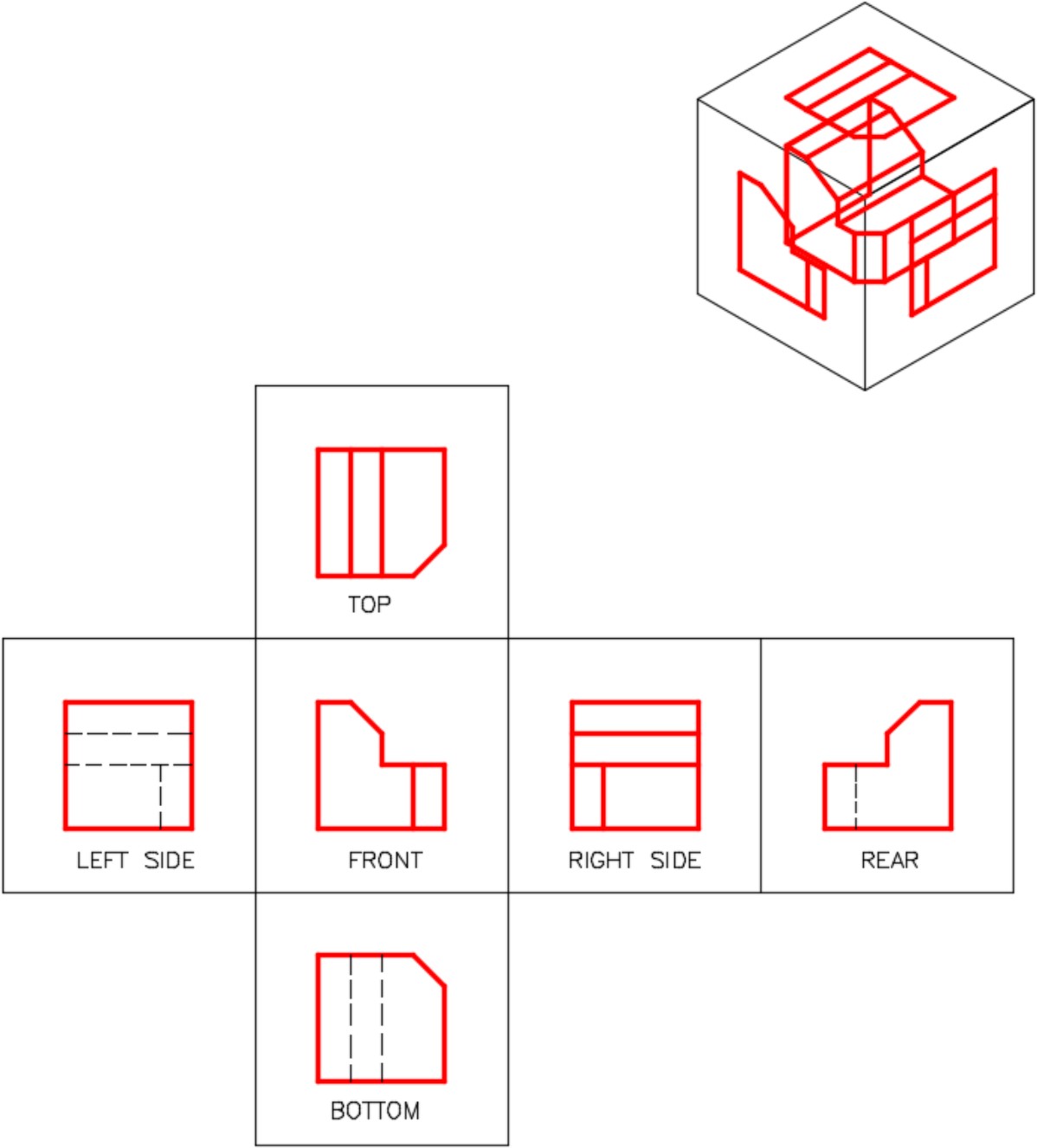
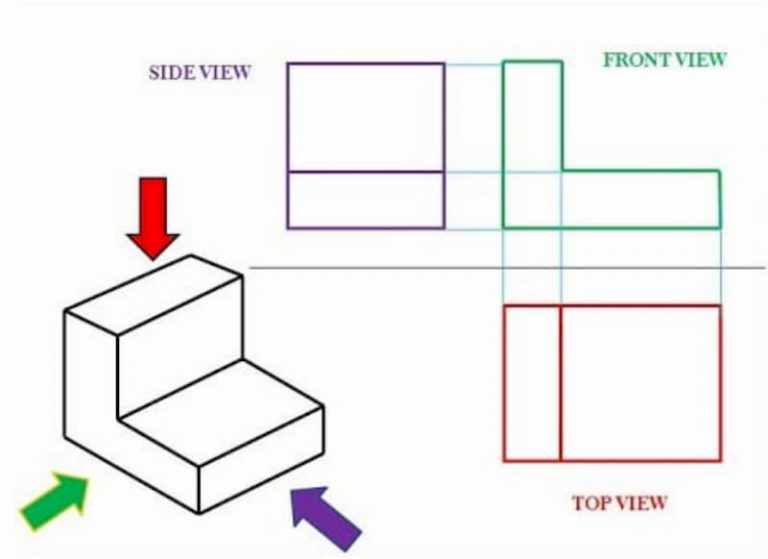
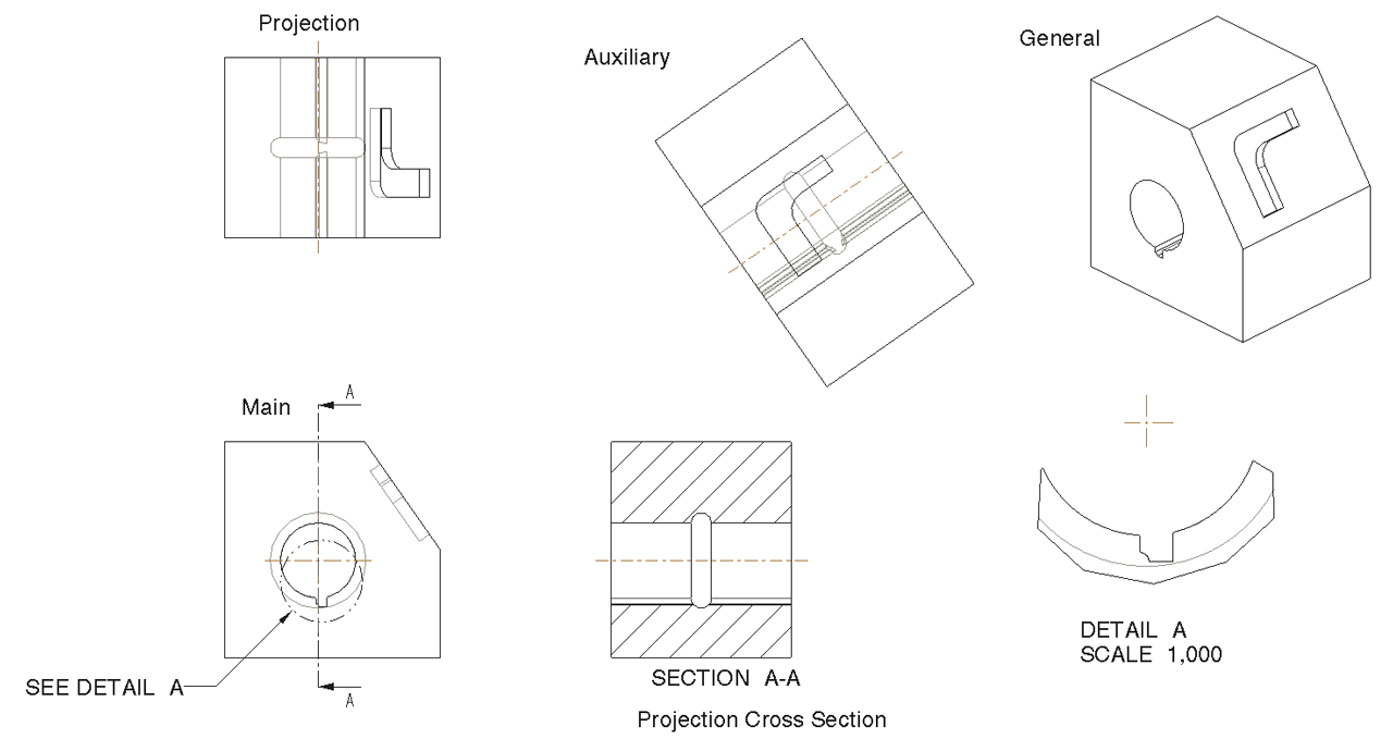
Types Of Views In Engineering Drawing - In addition, all of the views are aligned. Common mistakes in engineering drawing. Web the primary view types available in the view type menu (illustrated in figure below) are: Engineering drawing can be defined as a graphical language used by engineers and other technical personnel associated with the engineering profession. Orthographic views represent different sides of an object, typically the top view, front view, and side view. They retain the positions shown below from the glass box projection. In a full section view, the cutting plane makes a. Several systems of dimensioning and tolerancing have evolved. Web orthographic views allow us to represent a 3d object in 2d on a drawing. Web the video below covers the fundamentals, including the different types of views, first and third angle projection methods, dimensioning, tolerancing, best practices when creating drawings. Web the video below covers the fundamentals, including the different types of views, first and third angle projection methods, dimensioning, tolerancing, best practices when creating drawings. Web types of views used in drawings. Common mistakes in engineering drawing. It also provides a brief introduction to gd&t (geometric dimensioning and tolerancing). While three views are standard, keep in mind that there. Web understanding the types, principles, and significance of engineering drawing views empowers engineers and designers to communicate design intent effectively, visualize complex geometries accurately, and ensure manufacturability and compliance with industry standards. Web types of views. Web types of views used in drawings. This can be accomplished by providing a variety of views of different sides of an object in. In addition, all of the views are aligned. Before starting with this text, i suggest you familiarize yourself with the projection methods on engineering drawings. Web types of views. In a full section view, the cutting plane makes a. In an isometric drawing, the object’s vertical lines are drawn vertically, and the horizontal lines in the width and depth planes. The width dimension is common to the front and top views. It also provides a brief introduction to gd&t (geometric dimensioning and tolerancing). The representation of the object in figure 2 is called an isometric drawing. Web a section or cross section is a view generated from a part or assembly on a cutting plane or multiple cutting planes that. In addition, all of the views are aligned. They retain the positions shown below from the glass box projection. Before starting with this text, i suggest you familiarize yourself with the projection methods on engineering drawings. 8 tips for creating engineering drawing. The height dimension is common to the front and side views. Several systems of dimensioning and tolerancing have evolved. Sections normally comprise of two parts, firstly the section cut indicator with identification. The width dimension is common to the front and top views. There are three types of pictorial views: This method provides a comprehensive understanding of the object’s shape and dimensions. Web the following are the different types of views often used in engineering drawing: In a full section view, the cutting plane makes a. Web the three standard views are the top, front, and right side. You are sending a hand sketch with only outline dimensions to your supplier in the usa using the imperial system of unit measurements. Web. Common mistakes in engineering drawing. Web understanding the types, principles, and significance of engineering drawing views empowers engineers and designers to communicate design intent effectively, visualize complex geometries accurately, and ensure manufacturability and compliance with industry standards. In addition, all of the views are aligned. This method provides a comprehensive understanding of the object’s shape and dimensions. Web types of. How the views are laid out on a drawing depends on whether 3 rd angle or 1 st angle projection is being used. Web the video below covers the fundamentals, including the different types of views, first and third angle projection methods, dimensioning, tolerancing, best practices when creating drawings. Dth and depth planes are shown at 30 degrees to the. Web in this article, we will discuss the types of section views and detailed views that will assist us in clarifying our design intent. Dth and depth planes are shown at 30 degrees to the horizontal. The height dimension is common to the front and side views. Web the primary view types available in the view type menu (illustrated in. 8 tips for creating engineering drawing. Engineering drawing can be defined as a graphical language used by engineers and other technical personnel associated with the engineering profession. Isometric view (dimetric and trimetric view) orthographic view (front, side, top, bottom and back views) section view. It also provides a brief introduction to gd&t (geometric dimensioning and tolerancing). Orthographic views can show us an object viewed from each direction. Web the following are the different types of views often used in engineering drawing: How the views are laid out on a drawing depends on whether 3 rd angle or 1 st angle projection is being used. The two main types of views (or “projections”) used in drawings are: Web a section or cross section is a view generated from a part or assembly on a cutting plane or multiple cutting planes that reveals the outlines on the inside or assembly fits. In an isometric drawing, the object’s vertical lines are drawn vertically, and the horizontal lines in the width and depth planes are shown at 30 degrees to the horizontal. While three views are standard, keep in mind that there are many objects that only need two views and some that only need one view to describe it. Web without different views, engineering drawings cannot exist, so understanding how views are used on drawings is a critical. This can be accomplished by providing a variety of views of different sides of an object in a single image or by representing all three dimensions of an object in a single image. The two main types of views (or “projections”) used in drawings are: You can tell which angle projection is used by the symbol shown on the drawing. You are sending a hand sketch with only outline dimensions to your supplier in the usa using the imperial system of unit measurements.
Drawings Introduction to Engineering Design
_1660657970.png)
Learn How To Understand The Views of Engineering Drawings SkillLync
_1660658070.png)
Learn How To Understand The Views of Engineering Drawings SkillLync
_1660658250.png)
Learn How To Understand The Views of Engineering Drawings SkillLync

?What do you know about the engineering drawing « Ali's Engineering Design

Engineering Drawing Views & Basics Explained Fractory

types of section views in engineering drawing Zolocsik Colins
_1660658476.png)
Learn How To Understand The Views of Engineering Drawings SkillLync
_1660658414.png)
Learn How To Understand The Views of Engineering Drawings SkillLync

Engineering Drawing
Web Types Of Views.
Web In This Article, We Will Discuss The Types Of Section Views And Detailed Views That Will Assist Us In Clarifying Our Design Intent.
Sections Normally Comprise Of Two Parts, Firstly The Section Cut Indicator With Identification.
Orthographic Views Represent Different Sides Of An Object, Typically The Top View, Front View, And Side View.
Related Post: