Typ In Drawing, Such as a radius or chamfer which acts as relief and i am not concerned with having the dimension be exact or even fall within the given tolerances.
Typ In Drawing - Where a typical condition is noted, it should be understood that similar conditions are the same unless specifically detailed or noted otherwise. This list includes abbreviations common to the vocabulary of people who work with engineering drawings in the manufacture and inspection of parts and assemblies. Web typ is simply an abbreviation for “typical.” it’s added to a note that applies throughout the drawing and saves you from pointing to each instance. Web engineering drawing abbreviations and symbols are used to communicate and detail the characteristics of an engineering drawing. For example, if the drawing shows 8 holes on a bolt circle, and just one is dimensioned, with “typ” or “ (typ)” following the dimension label, it means that that hole is typical of all 8 holes; Web definition of typ (typical) in construction. Its proper use can greatly enhance the clarity and efficiency of construction drawings, leading to smoother project execution. Web the abbreviation “typ,” meaning “typical,” is a valuable tool in construction documentation, used to denote repeated elements or features within a project. A typical dimension callout will occasionally be followed by a 2x, 5x or similar, to specify the quantity of features which are tolerance the same. In other words, it means that the other 7 holes are that size also.' Web engineering drawing abbreviations and symbols are used to communicate and detail the characteristics of an engineering drawing. Web the abbreviation “typ,” meaning “typical,” is a valuable tool in construction documentation, used to denote repeated elements or features within a project. For example, if the drawing shows 8 holes on a bolt circle, and just one is dimensioned, with typ. Web typ means ‘other features share the same characteristic. The designation typ means typical on construction documents. To document say tooling changes on one that may not be needed on both drawings , (tool hole etc.)it just gives you better control of drawings. In other words, it means that the other 7 holes are that size also.’. For example, if. For example, if the drawing shows 8 holes on a bolt circle, and just one is dimensioned, with typ or (typ) following the dimension label, it means that that hole is typical of all 8 holes; Web typ means ‘other features share the same characteristic. In other words, it means that the other 7 holes are that size also.' This. Web typ is simply an abbreviation for “typical.” it’s added to a note that applies throughout the drawing and saves you from pointing to each instance. Web it is a good practice to have seperate drawings for l.h. Where a typical condition is noted, it should be understood that similar conditions are the same unless specifically detailed or noted otherwise.. Web typ means ‘other features share the same characteristic. This list includes abbreviations common to the vocabulary of people who work with engineering drawings in the manufacture and inspection of parts and assemblies. To document say tooling changes on one that may not be needed on both drawings , (tool hole etc.)it just gives you better control of drawings. In. In other words, it means that the other 7 holes are that size also.’. For example, if the drawing shows 8 holes on a bolt circle, and just one is dimensioned, with “typ” or “ (typ)” following the dimension label, it means that that hole is typical of all 8 holes; This is identical to a feature which is identified. Web the abbreviation “typ,” meaning “typical,” is a valuable tool in construction documentation, used to denote repeated elements or features within a project. Web typ means 'other features share the same characteristic. Plus you have geometry for assembly drawing. Web typ means ‘other features share the same characteristic. Where a typical condition is noted, it should be understood that similar. Web definition of typ (typical) in construction. In many instances there are details on the documents that will occur at several different locations, or in several different situations on. Web engineering drawing abbreviations and symbols are used to communicate and detail the characteristics of an engineering drawing. To document say tooling changes on one that may not be needed on. This list includes abbreviations common to the vocabulary of people who work with engineering drawings in the manufacture and inspection of parts and assemblies. Plus you have geometry for assembly drawing. Such as a radius or chamfer which acts as relief and i am not concerned with having the dimension be exact or even fall within the given tolerances. To. In other words, it means that the other 7 holes are that size also.' Web typ is simply an abbreviation for “typical.” it’s added to a note that applies throughout the drawing and saves you from pointing to each instance. Web typ means 'other features share the same characteristic. Its proper use can greatly enhance the clarity and efficiency of. For example, i might call out 1/8typ, meaning 'approximately' 1/8. Web i use typ on a drawing to indicate a rough dimension. Web typ means 'other features share the same characteristic. This is identical to a feature which is identified as 2x or 5x. For example, if the drawing shows 8 holes on a bolt circle, and just one is dimensioned, with typ or (typ) following the dimension label, it means that that hole is typical of all 8 holes; Web typ is simply an abbreviation for “typical.” it’s added to a note that applies throughout the drawing and saves you from pointing to each instance. Its proper use can greatly enhance the clarity and efficiency of construction drawings, leading to smoother project execution. Web typical on an engineering drawing identifies a repeated feature. To document say tooling changes on one that may not be needed on both drawings , (tool hole etc.)it just gives you better control of drawings. Web it is a good practice to have seperate drawings for l.h. In other words, it means that the other 7 holes are that size also.’. A typical dimension callout will occasionally be followed by a 2x, 5x or similar, to specify the quantity of features which are tolerance the same. For example, if the drawing shows 8 holes on a bolt circle, and just one is dimensioned, with “typ” or “ (typ)” following the dimension label, it means that that hole is typical of all 8 holes; Plus you have geometry for assembly drawing. Web engineering drawing abbreviations and symbols are used to communicate and detail the characteristics of an engineering drawing. Such as a radius or chamfer which acts as relief and i am not concerned with having the dimension be exact or even fall within the given tolerances.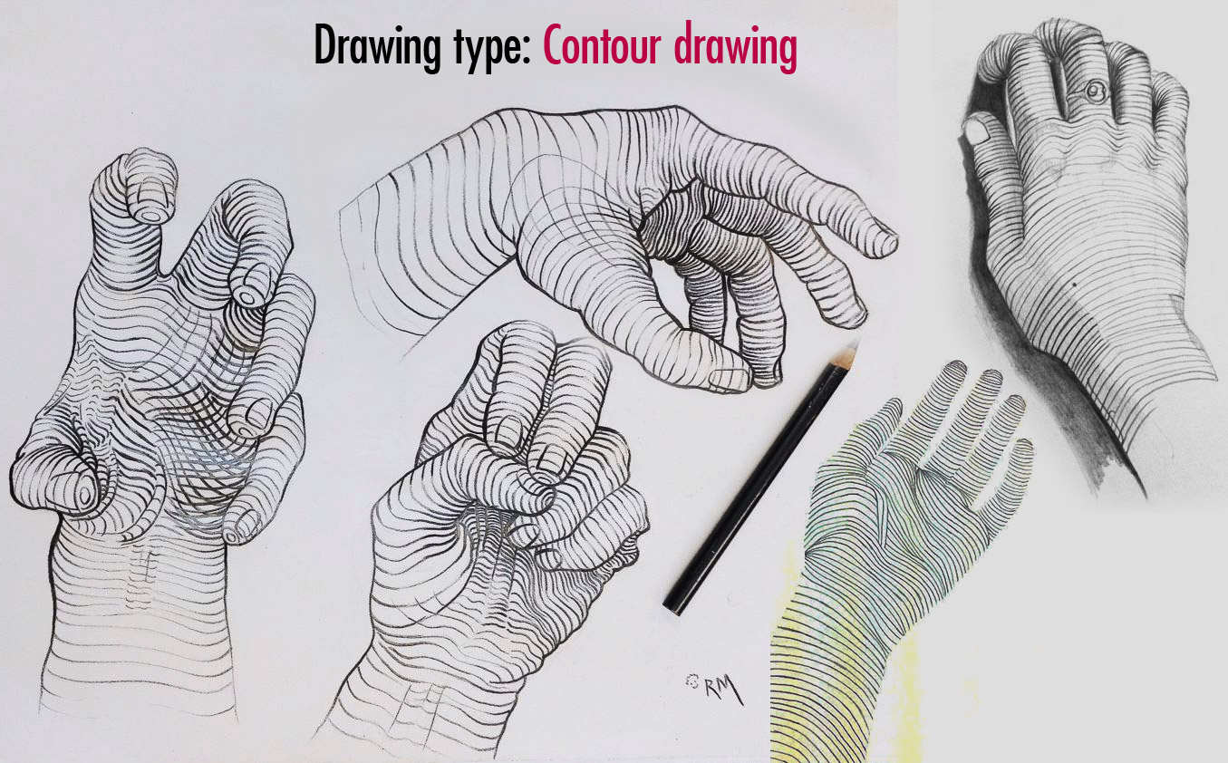
Different Drawing Types
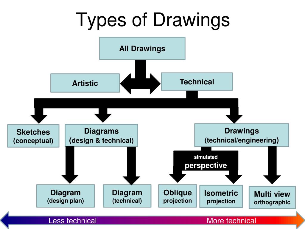
What Are The Different Types Of Technical Drawing Design Talk
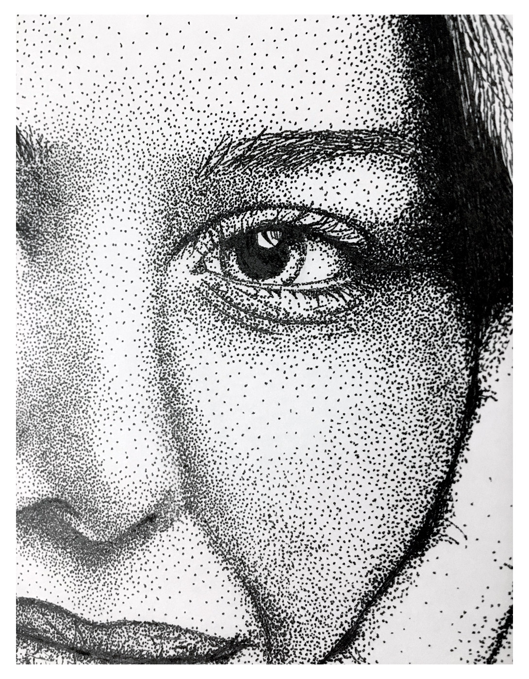
50 Different types of Drawing Styles Techniques and Mediums List from

Engineering drawing symbols TYP שרטוט סימון אוביקט טיפוסי YouTube
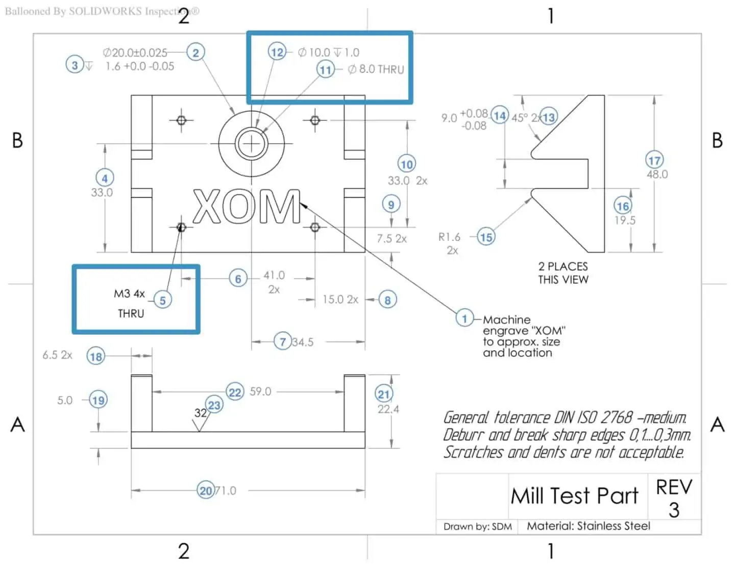
How To Prepare A Perfect Technical Drawing Xometry Europe

Technical Drawing Dimensions Design Talk

3 Types Of Engineering Drawings Printable Templates Free

What is TYP in Engineering Drawing. Engineering Drawing me TYP ka kya
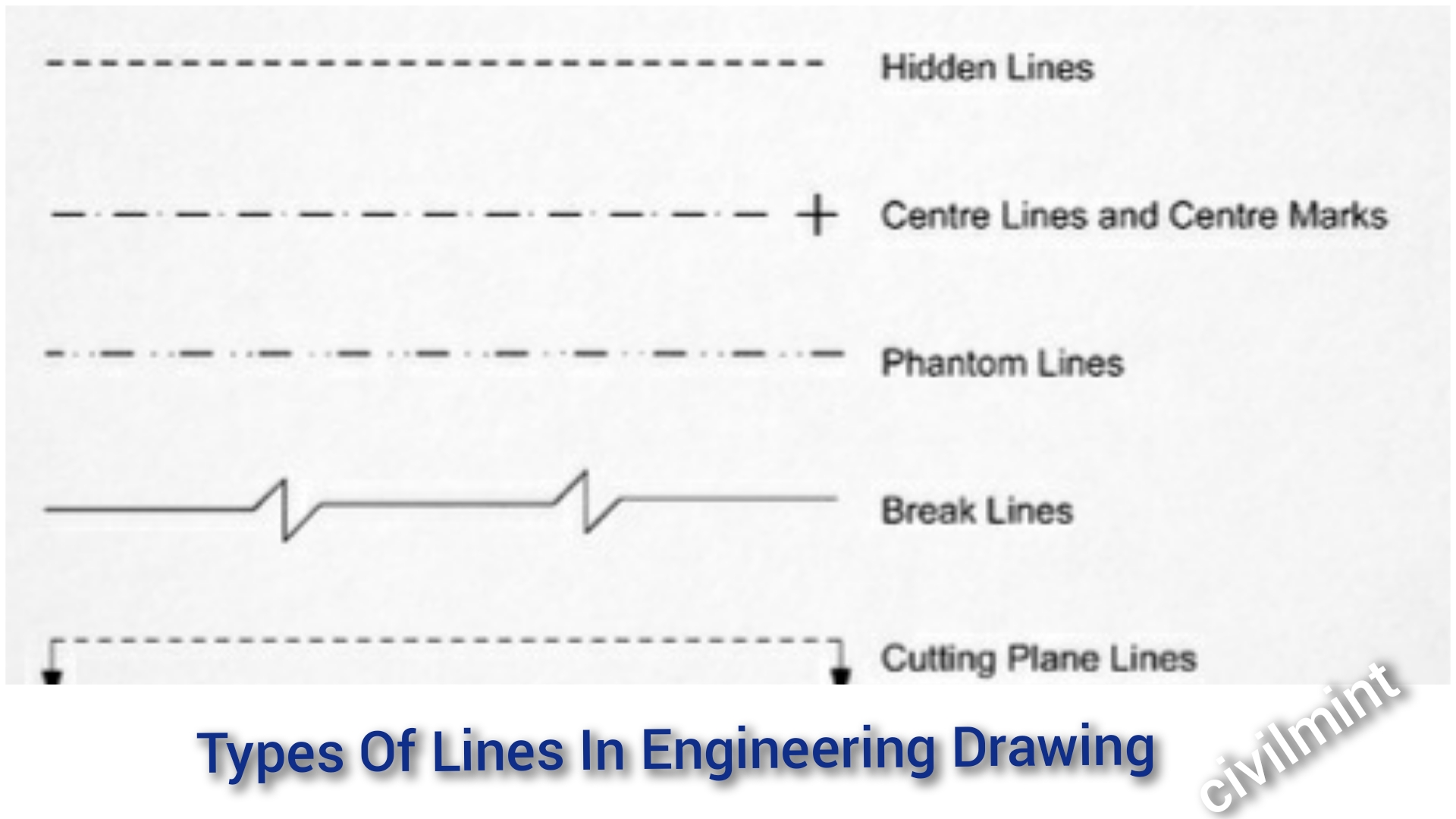
Types Of Lines In Engineering Drawing
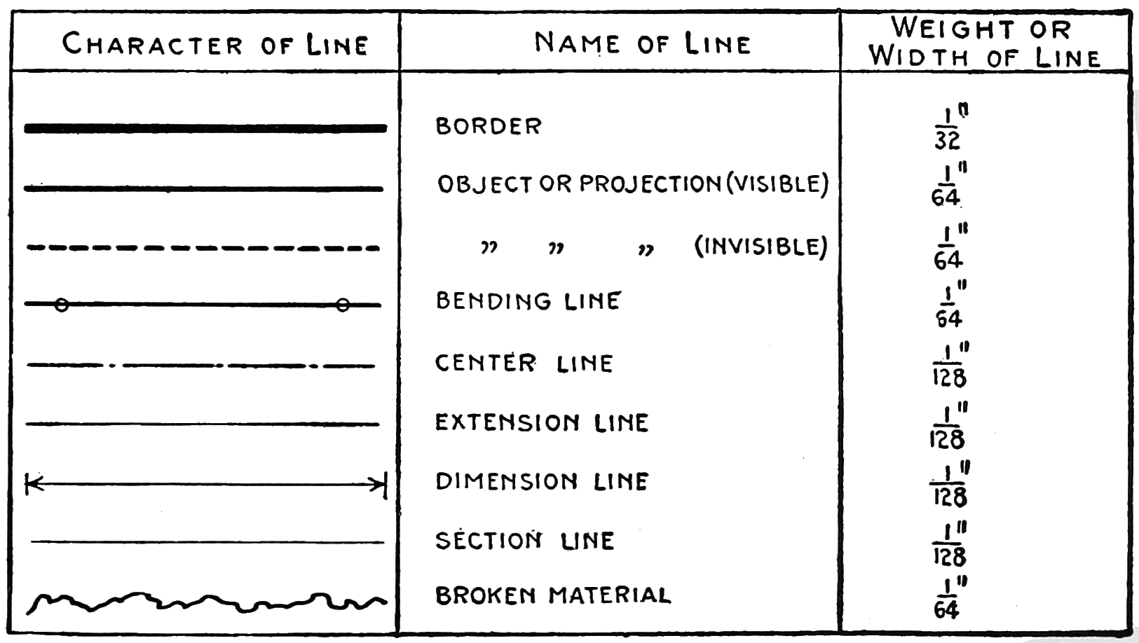
Different Line Types Used On Engineering Drawings Eng vrogue.co
This List Includes Abbreviations Common To The Vocabulary Of People Who Work With Engineering Drawings In The Manufacture And Inspection Of Parts And Assemblies.
In Many Instances There Are Details On The Documents That Will Occur At Several Different Locations, Or In Several Different Situations On.
Web Typ Means ‘Other Features Share The Same Characteristic.
Where A Typical Condition Is Noted, It Should Be Understood That Similar Conditions Are The Same Unless Specifically Detailed Or Noted Otherwise.
Related Post: