Symbol For Engineering Drawing, Here are the types of lines used in engineering drawing along with their details:
Symbol For Engineering Drawing - The true position theory and the specification of tolerance zones are also explained. A common use is to specify the geometry necessary for the construction of a component and is called a detail drawing. Work with runsom for your cnc programming projects. Web gd&t symbols, iso g&t symbols 1101 definitions. Web this chapter covers all of the major gd&t tools for engineering drawings including dimensions, tolerances, gd&t symbols, datums, feature control frames and more Basic types of symbols used in engineering drawings are countersink, counterbore, spotface, depth, radius, and diameter. Web the following is a short list of symbols that normally appear on a technical drawing and need understanding. Web engineering drawing is a graphical representation of an object or structure, which is used to communicate design and manufacturing details. Here are more commonly used engineering drawing symbols and design elements as below. How to read symbols in an engineering drawing? Web find common gd&t symbols in convenient charts broken down by their use in drawing and drafting. Unlike a model, engineering drawings note much more specific information and requirements, such as: This list includes abbreviations common to the vocabulary of people who work with engineering drawings in the manufacture and inspection of parts and assemblies. Web engineering drawings use standardised. It is a language of its own, with various types of lines and symbols used to convey specific information. Web the following is a short list of symbols that normally appear on a technical drawing and need understanding. Unlike a model, engineering drawings note much more specific information and requirements, such as: Web a convenient guide for geometric dimensioning and. Web this chapter covers all of the major gd&t tools for engineering drawings including dimensions, tolerances, gd&t symbols, datums, feature control frames and more Web just as an architectural drawing or blueprint shows you how to construct a building, an engineering drawing shows you how to manufacture a specific item or product. Why abbreviations and symbols are needed for engineering. Web this chapter covers all of the major gd&t tools for engineering drawings including dimensions, tolerances, gd&t symbols, datums, feature control frames and more Here are more commonly used engineering drawing symbols and design elements as below. Web just as an architectural drawing or blueprint shows you how to construct a building, an engineering drawing shows you how to manufacture. Web just as an architectural drawing or blueprint shows you how to construct a building, an engineering drawing shows you how to manufacture a specific item or product. Web gd&t symbols, iso g&t symbols 1101 definitions. Web engineering drawings use standardised language and symbols. Many of the definitions are not official asme, ansi or iso terminology. “learning gd&t from scratch,”. Web find common gd&t symbols in convenient charts broken down by their use in drawing and drafting. Web this chapter covers all of the major gd&t tools for engineering drawings including dimensions, tolerances, gd&t symbols, datums, feature control frames and more Web engineering drawing symbols and their meanings webthe comprehensive scope of this book encompasses topics including orthographic, isometric and. Various symbols and abbreviations in engineering drawings give you information about the dimensions, design, and materials used. “learning gd&t from scratch,” provided by keyence, walks you through the basics of geometric dimensioning and tolerancing, datums, and measurements by coordinate measuring. Web engineering drawing is a graphical representation of an object or structure, which is used to communicate design and manufacturing. How to read an engineering drawing symbol. This makes understanding the drawings simple with little to no personal interpretation possibilities. Unlike a model, engineering drawings note much more specific information and requirements, such as: Web this page explains the 16 symbols used in gd&t, and the classification thereof. Web the following is a list of symbols that are commonly found. Web engineering drawings use standardised language and symbols. Web engineering drawing is a graphical representation of an object or structure, which is used to communicate design and manufacturing details. Here are the types of lines used in engineering drawing along with their details: Various symbols and abbreviations in engineering drawings give you information about the dimensions, design, and materials used.. They are 1) piping and instrument drawings (p&ids), 2) electrical single lines and schematics, 3) electronic diagrams and schematics, 4) logic diagrams and prints, and 5) fabrication, construction, and architectural drawings. Web engineering drawings use standardised language and symbols. Web engineering drawing symbols and their meanings webthe comprehensive scope of this book encompasses topics including orthographic, isometric and oblique projections,. Click on the links below to learn more about each gd&t symbol or concept, and be sure to download the free wall chart for a quick reference when at. The true position theory and the specification of tolerance zones are also explained. Various symbols and abbreviations in engineering drawings give you information about the dimensions, design, and materials used. How to read an engineering drawing symbol. This list includes abbreviations common to the vocabulary of people who work with engineering drawings in the manufacture and inspection of parts and assemblies. So let’s look at the different line and view types you will come across in the engineering discipline. You can also check out the gd&t symbols and terms on our site. Web the following is a short list of symbols that normally appear on a technical drawing and need understanding. Web an engineering drawing is a type of technical drawing that is used to convey information about an object. Engineering drawing symbols play a vital role in communication among engineers and other stakeholders involved in the design and construction process. Web gd&t symbols, iso g&t symbols 1101 definitions. Various symbols and abbreviations in engineering drawings give you information about the dimensions, design, and materials used. Web engineering drawings use standardised language and symbols. Unlike a model, engineering drawings offer more specific detail and requirements, such as: Many of the definitions are not official asme, ansi or iso terminology. Web the following is a list of symbols that are commonly found in engineering drawings: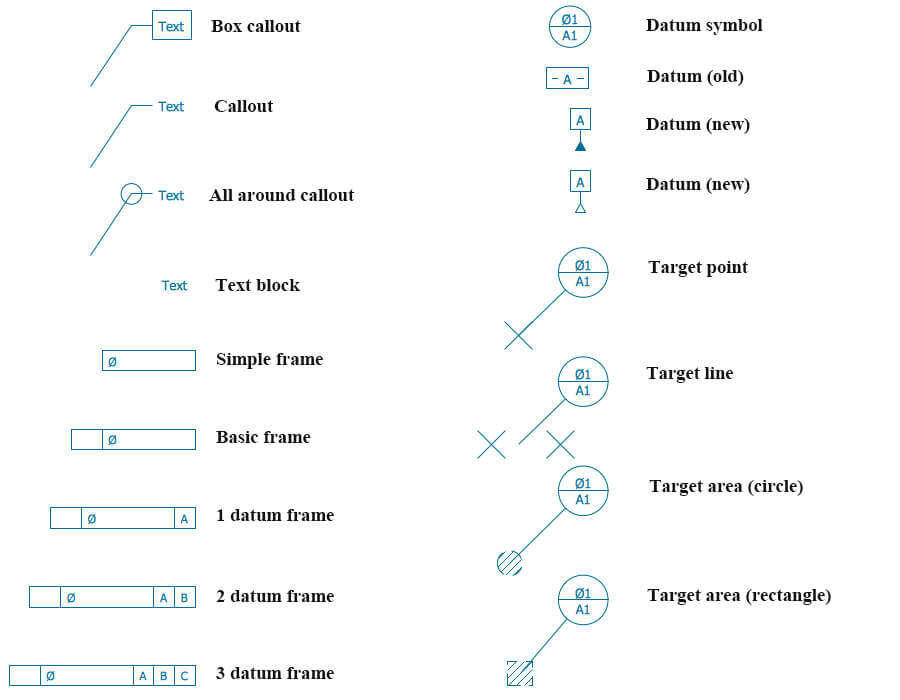
Mechanical Engineering Design Symbols

Engineering Drawing important Symbol for Mechanical Trade YouTube
Mechanical Engineering Drawing Symbols Pdf Free Download at
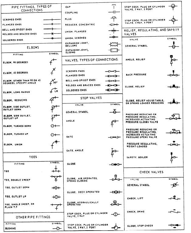
Engineering Drawing Symbols And Their Meanings Pdf at PaintingValley

Standard Engineering Drawing Symbols
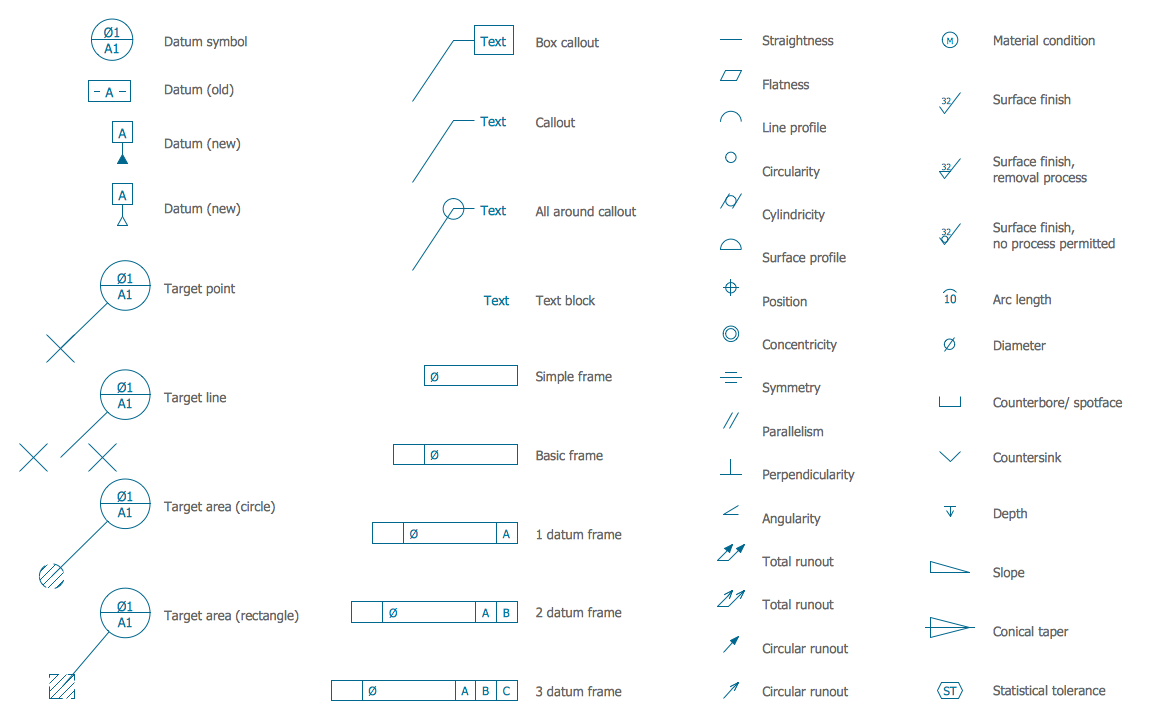
Standard Engineering Drawing Symbols
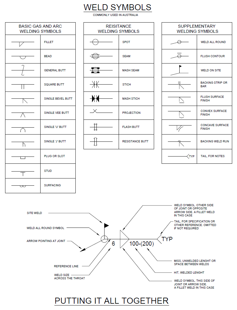
Engineering Drawing Symbols And Their Meanings Pdf at PaintingValley
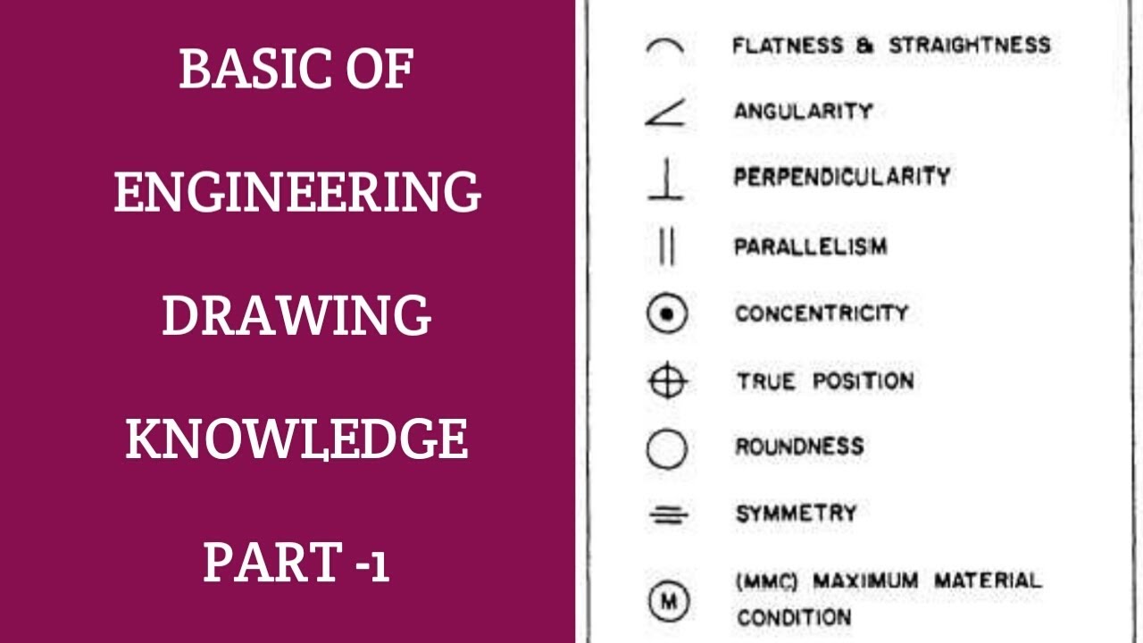
Engineering Drawing Symbols And Their Meanings Pdf at PaintingValley
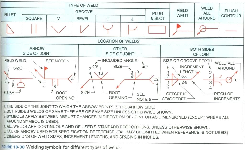
Engineering Drawing Symbols And Their Meanings Pdf at PaintingValley
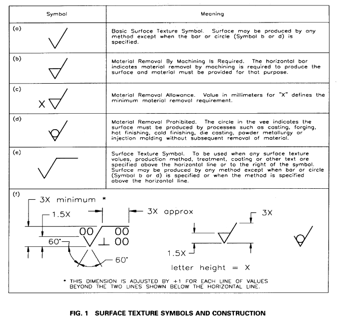
Surface roughness symbol (in drawings) Mechanical engineering general
Web What Are The Most Commonly Used Engineering Drawing Symbols And Their Meanings?
Here Are More Commonly Used Engineering Drawing Symbols And Design Elements As Below.
Web Find Common Gd&T Symbols In Convenient Charts Broken Down By Their Use In Drawing And Drafting.
The Following Are Definitions Commonly Used Throughout Industry When Discussing Gd&T Or Composing Engineering Drawing Notes.
Related Post: