Section Line In Engineering Drawing, Web in short, a section drawing is a view that depicts a vertical plane cut through a portion of the project.
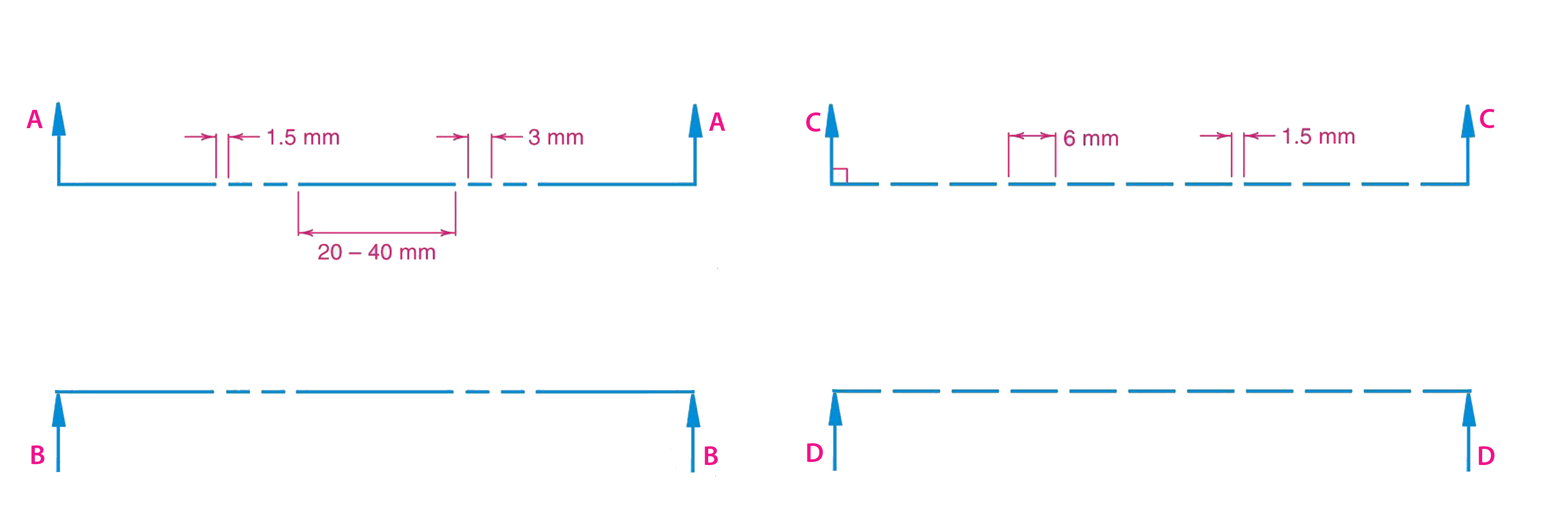
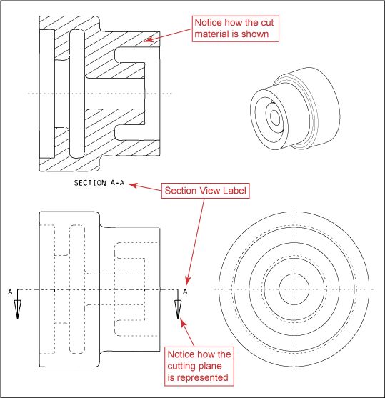
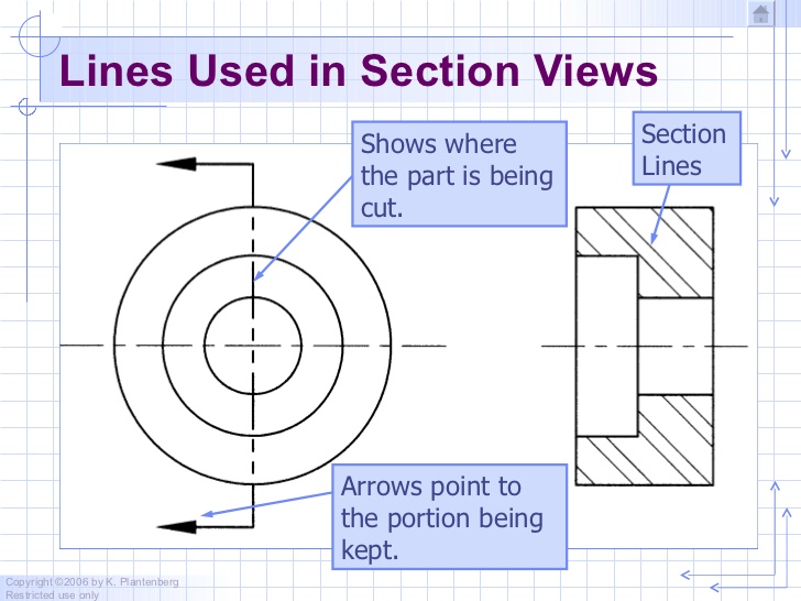
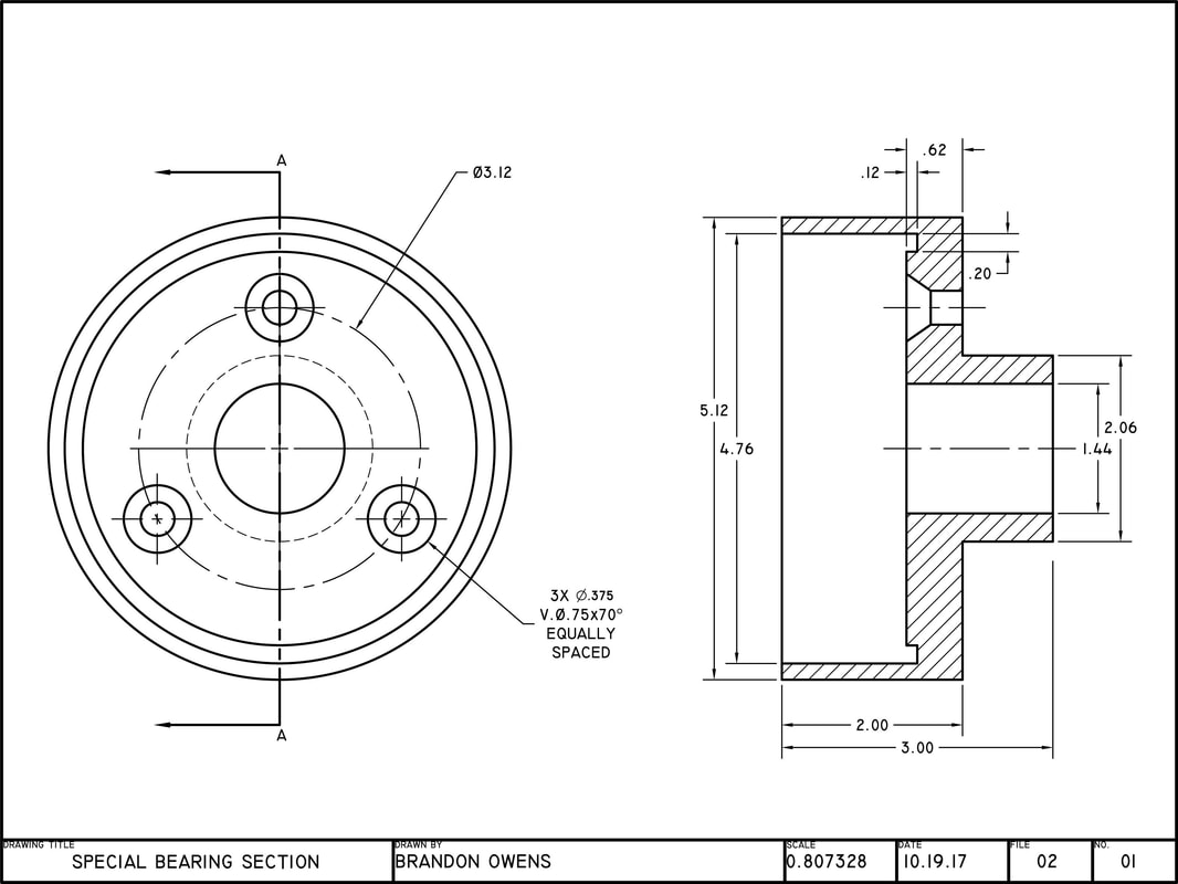
Section Line In Engineering Drawing - Web a detailed explanation of section drawings: Web section lines are used to show the cut surfaces of an object in section views. Section lines are generally drawn at a 45° angle. Various types of section lines may indicate the type of material cut by the cutting plane line. When sketching an object or part that requires a sectional view, they are drawn by eye at an angle of approximately 45 degrees, and are spaced about 1/8” apart. Space between lines = 3/4 h. Arrows indicate the direction of view. Web a section is used to show the detail of a component, or an assembly, on a particular plane which is known as the cutting plane. Web this section will cover the different types of section views, corresponding technical vocabulary, and help you determine which section view would best communicate important aspects of an object or assembly to others. A freehand thick line, and a long, ruled thin line with zigzags. Section line, section reference arrow, section reference letters, hatch. Center lines are used to indicate the centers of holes, arcs, and symmetrical objects. Section lines are thin and the symbols (type of lines) are chosen according to the material of the object. Section lines are very light. Web a section is used to show the detail of a component, or. The line that indicates the plane where the cut is made is called the section line. When sketching an object or part that requires a sectional view, they are drawn by eye at an angle of approximately 45 degrees, and are spaced about 1/8” apart. Web the most common is a continuous line, also known as a drawing line. Web. Web a section is used to show the detail of a component, or an assembly, on a particular plane which is known as the cutting plane. Section views are used to supplement standard orthographic view drawings in order to completely describe an object. Web the picture below shows how our object would be represented in the engineering drawing. Since they. The main elements of the section view are: The spacing of section lines is equal or uniform on a section view. Used to indicate where the cutting plane cuts the material. They are fine, dark lines. These views are usually represented via annotated section lines and labels on the projects floor plans, showing the. Section views are used to supplement standard orthographic view drawings in order to completely describe an object. Web section lines on a drawing indicate a surface that has been cut or sliced in a section view. A simple bracket is shown in fig. 8.1 and it is required to draw three sectional views. A freehand thick line, and a long,. Used to indicate where the cutting plane cuts the material. Web the general purpose or cast iron section line is drawn at a 45 degree angle and spaced 1/16 (1.5mm) to 1/8 (3mm) or more depending on the size of the drawing, but can be changed when adjacent parts are in section. Web here are a few examples: Space between. The main elements of the section view are: For most purposes, the general use symbol of cast iron is used. Section line, section reference arrow, section reference letters, hatch. This helps to identify the plane in which the part or assembly is cut. Put simply, these lines are for drawing objects. Web sectional cutting planes are indicated with a thin chain line with thick ends. Web the diagonal lines on the section drawing are used to indicate the area that has been theoretically cut. The line that indicates the plane where the cut is made is called the section line. Web section lines are used to show the cut surfaces of. The detail of an object can be shown by drawing a limited number of carefully chosen views and showing external features of the object by firm lines and invisible detail by. A freehand thick line, and a long, ruled thin line with zigzags. Put simply, these lines are for drawing objects. Web drawing numbers, title block and letters denoting cutting. Web section cut indicators identifies the plane where, how and on which planes the section cut is made. Arrows indicate the direction of view. This helps to identify the plane in which the part or assembly is cut. 8.1 and it is required to draw three sectional views. Section lines, or hatching, that represent the cut surface usually consist of. Web drawing numbers, title block and letters denoting cutting planes, sections are written in. Web the diagonal lines on the section drawing are used to indicate the area that has been theoretically cut. Section lines, or hatching, that represent the cut surface usually consist of thin parallel lines, as shown below, drawn at an angle of approximately 45° to the principal edges or axes of the part. Web section cut indicators identifies the plane where, how and on which planes the section cut is made. Arrows indicate the direction of view. This helps to identify the plane in which the part or assembly is cut. Web the most common is a continuous line, also known as a drawing line. Web sectional cutting planes are indicated with a thin chain line with thick ends. Web a section is used to show the detail of a component, or an assembly, on a particular plane which is known as the cutting plane. Web here are a few examples: This represents the physical boundaries of an object. Space between lines = 3/4 h. Web a detailed explanation of section drawings: Section lines are thin and the symbols (type of lines) are chosen according to the material of the object. Web section lining is a method of representing internal features of an object in an engineering drawing. A simple bracket is shown in fig.
Engineering Drawing Tutorials/Orthographic and sectional views ( T 11.1
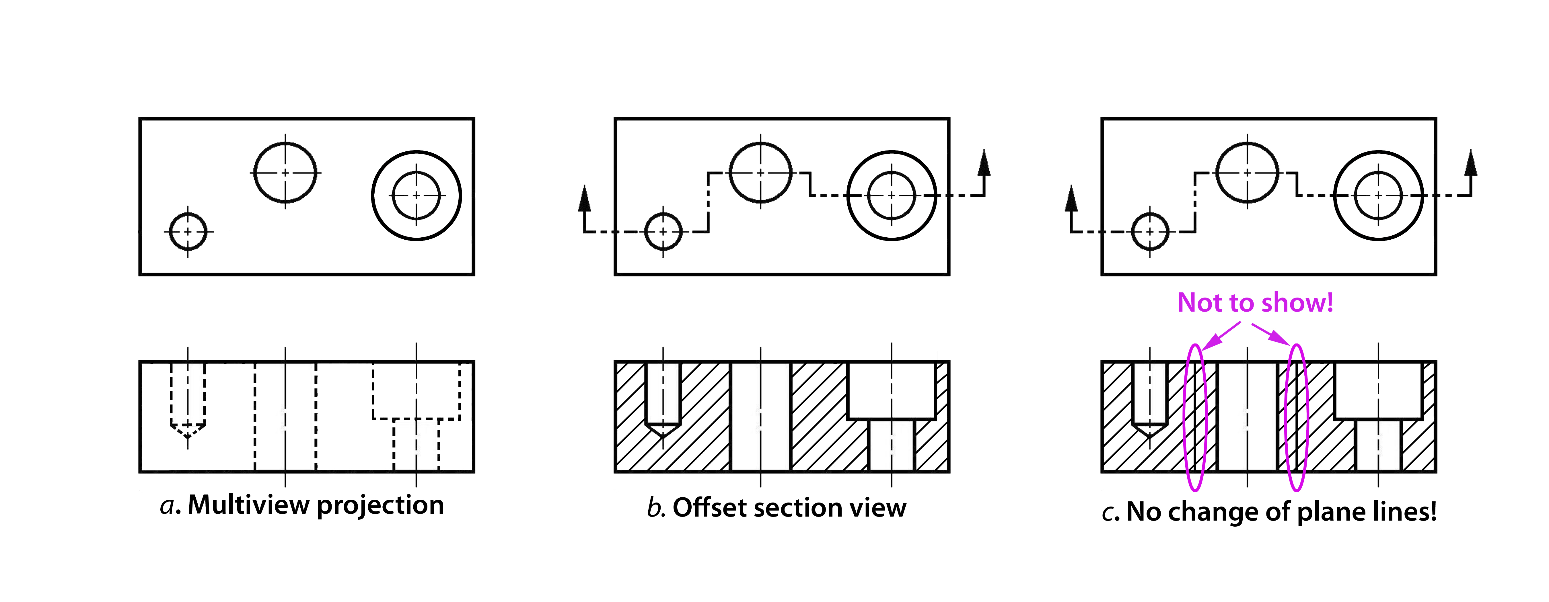
Sectioning Technique Engineering Design McGill University
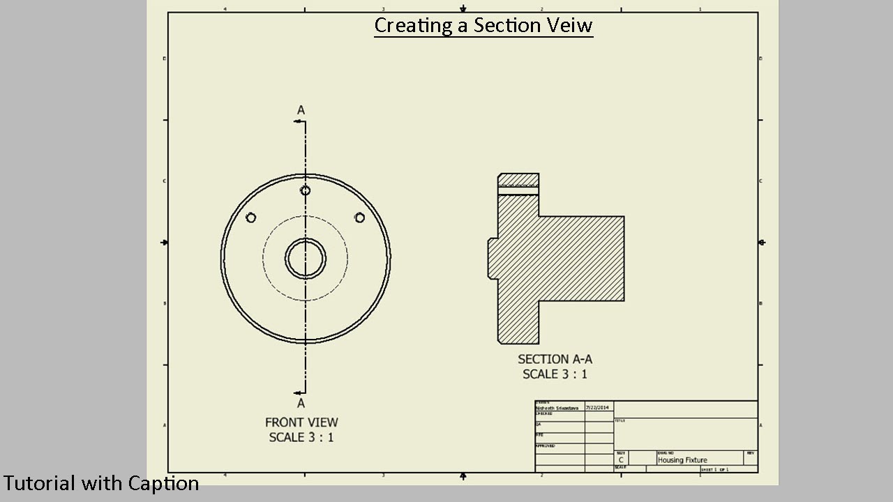
Sectional View Engineering Drawing Exercises at GetDrawings Free download

Full Sectioning Problem 1 Engineering Drawing 9.1 YouTube
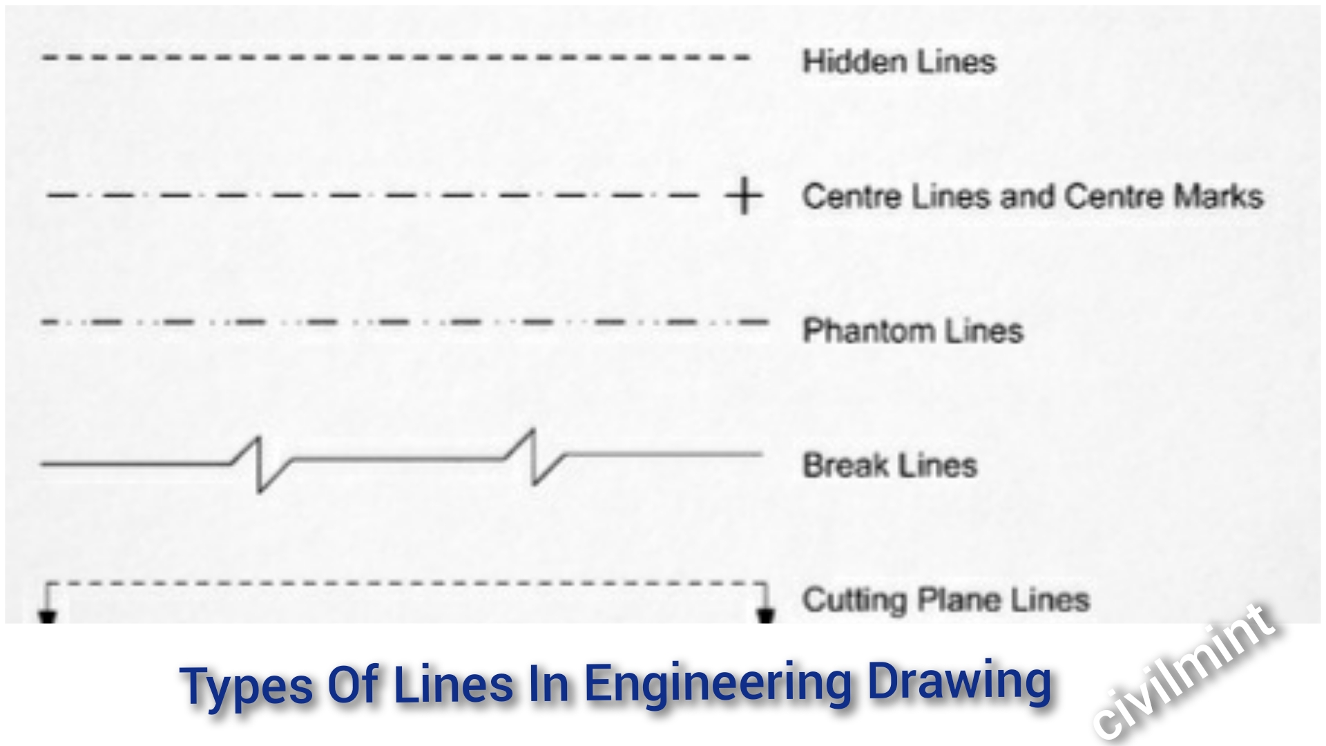
Types Of Lines In Engineering Drawing
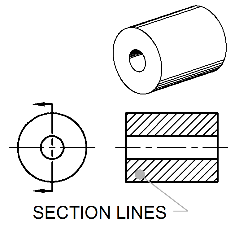
Section Lines ToolNotes
Sectioning Technique Engineering Design McGill University
Sectional Views
Sectional View Engineering Drawing Exercises at GetDrawings Free download
SECTION DRAWINGS BRANDON OWENS' PORTFOLIO
If The Cut Line Is On More Than One Plane, The Change In Direction Should Also Be Indicated With Thicker Ends.
Web Theory Of Sectioning:
They Improve Visualization Of Designs, Clarify Multiviews And Facilitate Dimensioning Of Drawings.
Web Section Lines And Symbols.
Related Post: