Isometric Piping Drawing Symbols, Specifies the ratio of the drawing’s size to the actual size of the components.
Isometric Piping Drawing Symbols - Learn what is piping isometric drawing, how to read it, and what symbols and calculations are used. Indicates the orientation of the drawing about the cardinal directions. 1.2 this set of standard symbols is intended for use on piping system diagrammatics. Reading tips, symbols, and drawing techniques for engineers and piping professionals. Find out the importance of isometric drawings for ndt, design,. See examples of piping isometric drawings and coordinate. The direction should be selected so as to facilitate easy checking of isometrics with ga. Shop our huge selectiondeals of the dayread ratings & reviewsfast shipping Location and direction help to properly orient the isometric drawing. It is not drawn to the scale, but it is proportionate with the. 1.2 this set of standard symbols is intended for use on piping system diagrammatics. Piping isometrics, commonly referred to as isos, are encountred nowadays throughout all process industries such as oil & gas, chemical, pharmaceutical or food. See sample isometric drawings and calculations for pipe length and offset. The direction should be selected so as to facilitate easy checking of. Indicates the orientation of the drawing about the cardinal directions. Web learn what piping isometric drawings are, how they are used, and how to read them. It is not drawn to the scale, but it is proportionate with the. Web an isometric drawing (or “iso”) is a pictorial view of one pipe, using isometric projection conventions to present a 2d. Web piping and instrumentation diagrams (p&ids) are articulate drawings of a processing plan with various symbols and abbreviations that entail the piping and. It provides diagrams and explanations of various piping components and. Web piping isometric dwg symbols designed just for you in autocad. Web learn what piping isometrics are, how they differ from orthographic views, and how to read. Web master piping isometrics with our comprehensive guide: More than 350 illustrations and photographs provide examples. Web the document appears to be a 21 page website on isometric piping symbols from cadcells.com. See examples of isometric drawings for piping systems in. Web learn what piping isometric drawings are, how they are used, and how to read them. Reading tips, symbols, and drawing techniques for engineers and piping professionals. Web an isometric drawing (or “iso”) is a pictorial view of one pipe, using isometric projection conventions to present a 2d view of a 3d pipe (fig. Web learn the basics of piping isometric drawings, technical illustrations that show a 3d view of piping systems. Web learn what piping. 1.2 this set of standard symbols is intended for use on piping system diagrammatics. Web the following information must be included in piping isometric drawings: Piping isometrics, commonly referred to as isos, are encountred nowadays throughout all process industries such as oil & gas, chemical, pharmaceutical or food. Learn what is piping isometric drawing, how to read it, and what. Specifies the ratio of the drawing’s size to the actual size of the components. How do isometrics look like ? Web learn the basics of piping isometric drawings, technical illustrations that show a 3d view of piping systems. Web it includes instructions for the proper drawing of symbols for fittings, flanges, valves, and mechanical equipment. Find out the importance of. Learn what is piping isometric drawing, how to read it, and what symbols and calculations are used. Reading tips, symbols, and drawing techniques for engineers and piping professionals. See examples of piping isometric drawings and coordinate. Location and direction help to properly orient the isometric drawing. Web find mechanical symbols for isometric drawings of piping systems, such as pipes, flanges,. Find out how to draw, read, and understand the. See sample isometric drawings and calculations for pipe length and offset. Location and direction help to properly orient the isometric drawing. Web the document appears to be a 21 page website on isometric piping symbols from cadcells.com. The direction should be selected so as to facilitate easy checking of isometrics with. How do isometrics look like ? In this dwg file you will find a huge collection of pipeline isometric drawings which are. Web piping and instrumentation diagrams (p&ids) are articulate drawings of a processing plan with various symbols and abbreviations that entail the piping and. Web the document appears to be a 21 page website on isometric piping symbols from. Specifies the ratio of the drawing’s size to the actual size of the components. Web learn how to read and create isometric drawings of piping systems using iso standard symbols. Piping isometrics, commonly referred to as isos, are encountred nowadays throughout all process industries such as oil & gas, chemical, pharmaceutical or food. More than 350 illustrations and photographs provide examples. Web piping and instrumentation diagrams (p&ids) are articulate drawings of a processing plan with various symbols and abbreviations that entail the piping and. Various symbols are used to indicate piping components, instrumentation, equipments in engineering drawings such as piping and instrumentation diagram. Web master piping isometrics with our comprehensive guide: Web learn the basics of piping isometric drawings, technical illustrations that show a 3d view of piping systems. Web isometric drawing symbols for valves. It provides diagrams and explanations of various piping components and. Web learn what piping isometric drawings are, how they are used, and how to read them. In this dwg file you will find a huge collection of pipeline isometric drawings which are. 1.2 this set of standard symbols is intended for use on piping system diagrammatics. See sample isometric drawings and calculations for pipe length and offset. Web isometric drawing symbols for piping fittings. Sometimes piping isometrics are also known as pipe fitting isometric drawings.
Sample isometric drawing for piping klowebcam
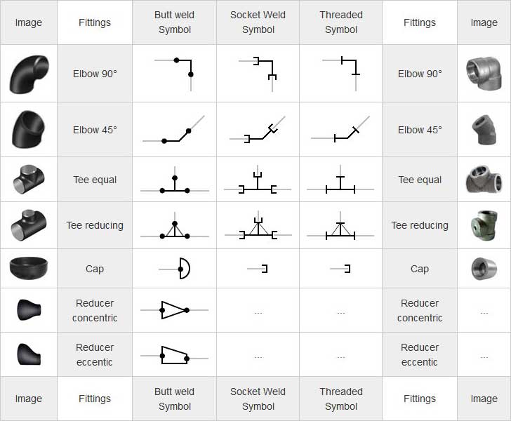
Piping Coordination System Mechanical symbols for Isometric drawings
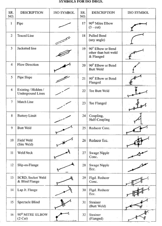
Piping Isometric Drawings The Piping Engineering World

How to read isometric drawing piping dadver

What is Piping Isometric drawing? How to Read Piping Drawing? ALL
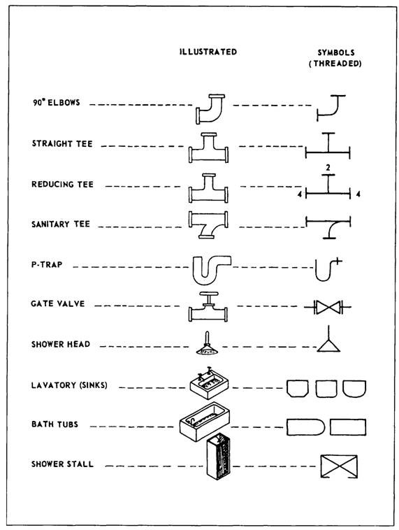
Piping Isometric Drawing Symbols Pdf at Explore
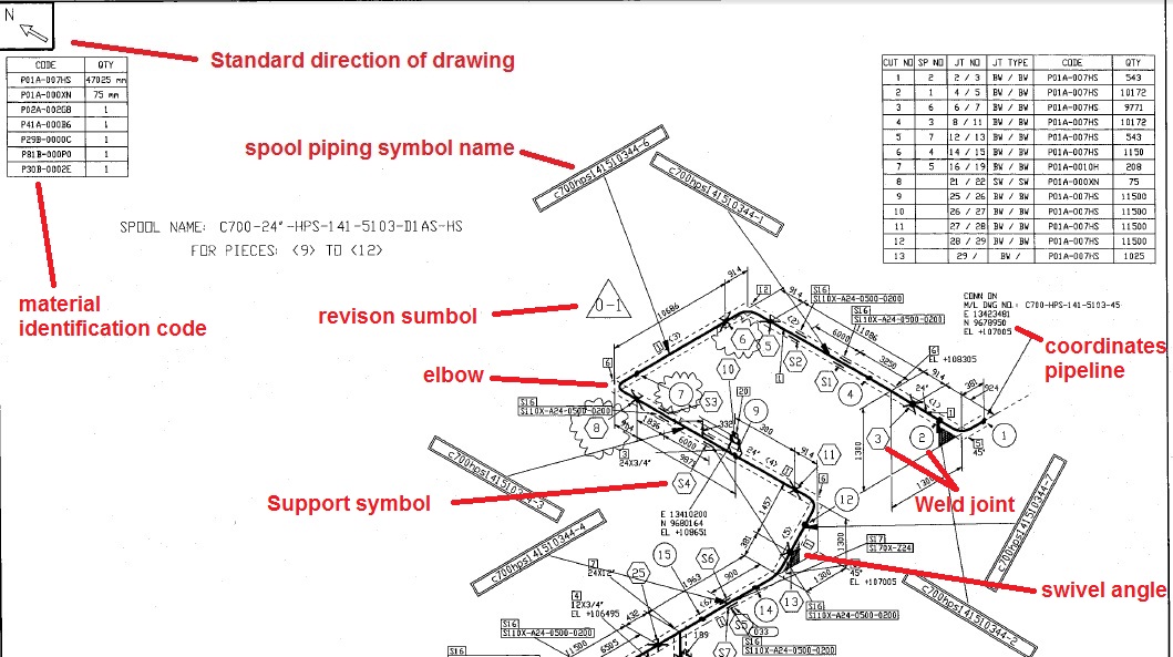
Piping Isometric Drawing Symbols Pdf at GetDrawings Free download
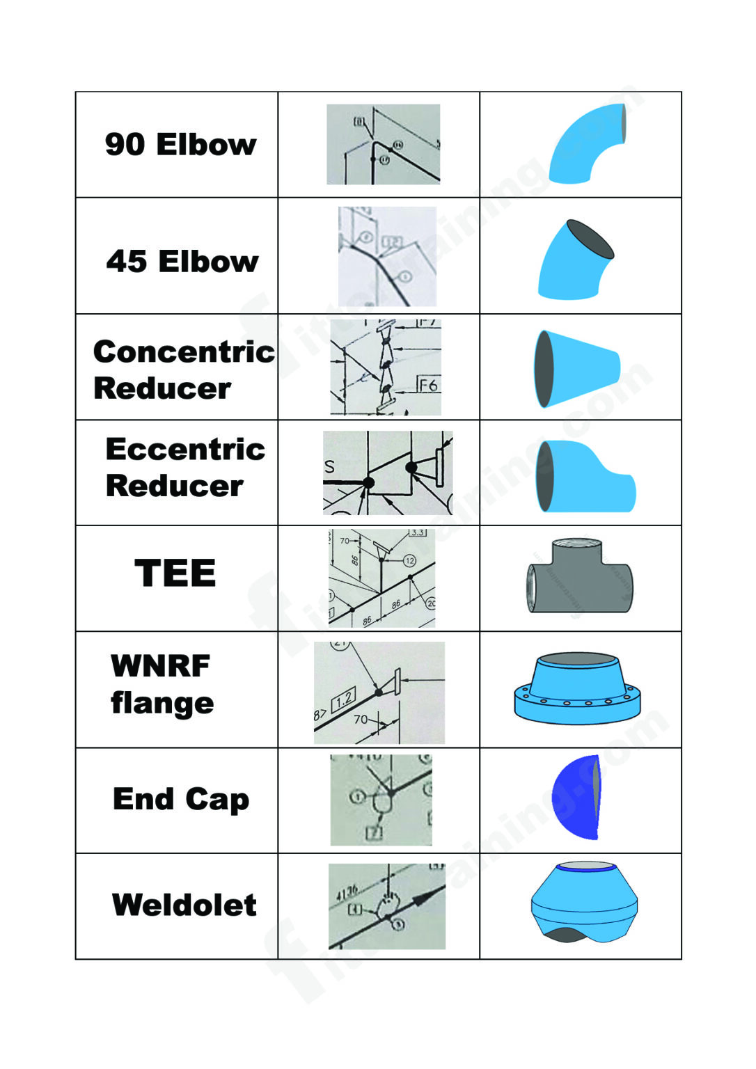
isometric pipe drawing fittings symbol Fitter training

Piping Isometric DWG Symbols Free Download Drawing in CAD
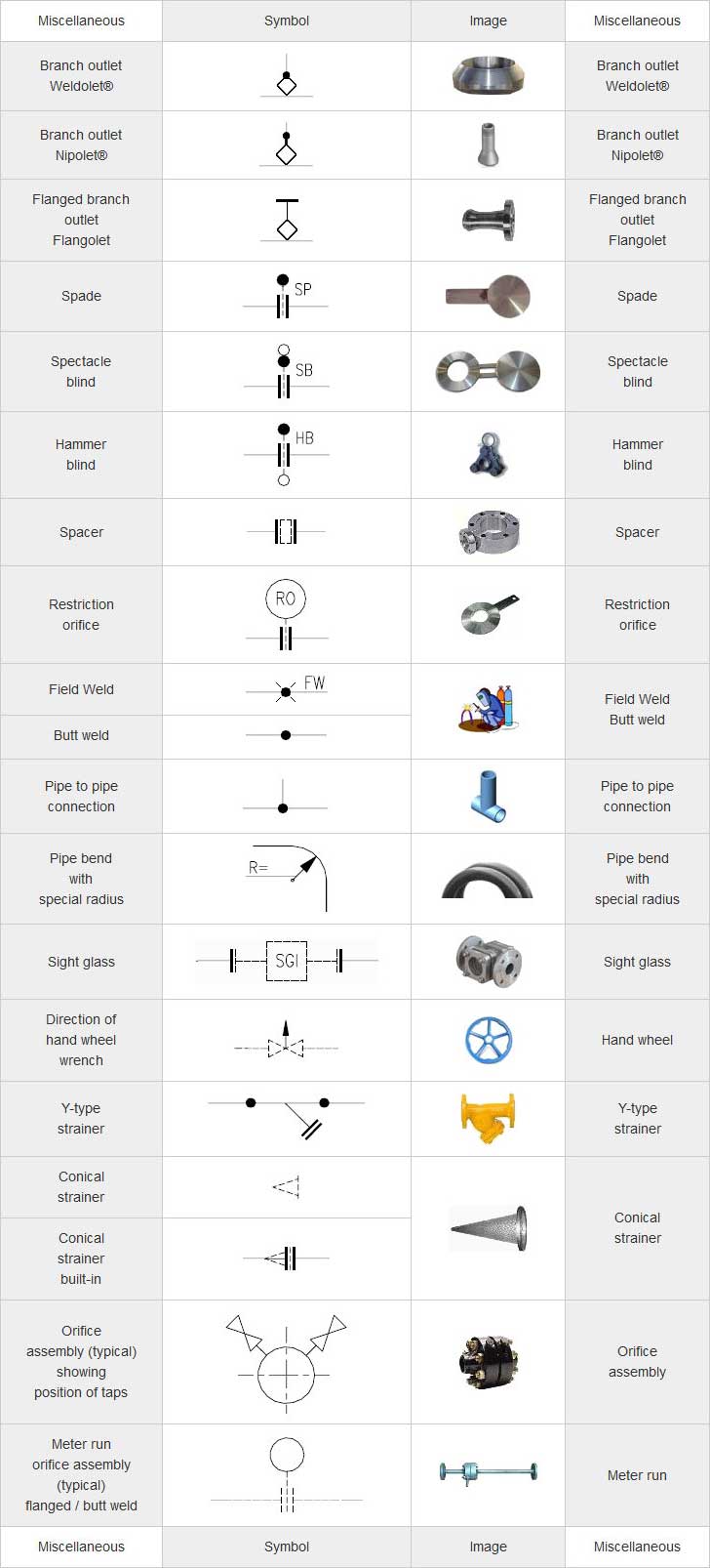
Piping Coordination System Mechanical symbols for Isometric drawings
Location And Direction Help To Properly Orient The Isometric Drawing.
See Examples Of Piping Isometric Drawings And Coordinate.
See Examples Of Isometric Drawings For Piping Systems In.
Web The Document Appears To Be A 21 Page Website On Isometric Piping Symbols From Cadcells.com.
Related Post: