Electric Outlet Drawing, Electrical diagram symbols often use arrows to indicate the direction of.
Electric Outlet Drawing - Web knowing how to read electrical symbols can help you identify types of components (resistors, inductors, capacitors, etc.) and their placement in a circuit. Chapter 5 general building heights and areas. Knowing the diagram of an electrical outlet can help you troubleshoot any issues with the wiring. Web roomsketcher's electrical drawing software offers a wide range of useful symbols for creating accurate and detailed electrical drawings, including switches, receptacle outlets, lighting symbols, and more. Electrical plan symbols used in electrical drawings, including power, lighting, security, fire alarm, and communications symbols. Web this technique only works if you can use an electrical outlet as a power source that’s opposite, or nearly opposite, the place where you want your new wall outlet. Wiring diagrams use simplified symbols to represent switches, lights, outlets, etc. Any electrical work, from installing a few new outlets to adding a new room, requires wiring. Schedules help to find the details of the equipment or fixtures used on the plans. Chapter 1 scope and administration. Chapter 5 general building heights and areas. Web knowing how to read electrical symbols can help you identify types of components (resistors, inductors, capacitors, etc.) and their placement in a circuit. Web wiring diagrams for outlets. Schedules help to find the details of the equipment or fixtures used on the plans. Fantasy 5 drawings are held daily at 1:05 p.m. An electrical drawing is a type of technical drawing that represents information for power, lighting, and communication in an engineering or architectural project. This guide includes what you need to know, plus steps for adding an electrical outlet by running the line behind your walls. Web this video covers the essentials of installing a gfci outlet (or gfci receptacle), including. Web outlet symbols used in electrical construction and reading and understanding blueprints and electrical wiring drawings. The most commonly used electrical blueprint symbols including plug outlets, switches, lights and other special symbols such as door bells and smoke detectors are shown in the figure below. Web wiring diagrams for outlets. Winners have 180 days from the draw date to claim. Electrical diagram symbols often use arrows to indicate the direction of. Wiring multiple light 3 way switches. Grounded and ungrounded duplex outlets, ground fault circuit interrupters (gfci), 20amp, 30amp, and 50amp receptacles for. Web knowing how to read electrical symbols can help you identify types of components (resistors, inductors, capacitors, etc.) and their placement in a circuit. This spacing is. Web electrical outlet (nec) is also known as receptacle and more commonly a socket outlet (iec). Electrical diagram symbols often use arrows to indicate the direction of. Web this video covers the essentials of installing a gfci outlet (or gfci receptacle), including line vs load terminals, wiring basics, why back wiring is ok and. Schedules help to find the details. Web this video covers the essentials of installing a gfci outlet (or gfci receptacle), including line vs load terminals, wiring basics, why back wiring is ok and. Winners have 180 days from the draw date to claim their prize. It also provides information on the type of connections used, the voltage, and the polarity of the wiring. Wiring multiple light. Web an electrical floor plan (sometimes called an electrical layout drawing or wiring diagram) is a detailed and scaled diagram that illustrates the layout and placement of electrical components, fixtures, outlets, switches, and wiring within a building or space. Florida man allegedly leads deputies on 2 mph 'chase' in stolen electric walmart scooter. Grounded and ungrounded duplex outlets, ground fault. Fantasy 5 drawings are held daily at 1:05 p.m. An electrical drawing is a type of technical drawing that represents information for power, lighting, and communication in an engineering or architectural project. Web helpful tools for architects and building designers. Web this page contains wiring diagrams for most household receptacle outlets you will encounter including: Electrical diagram symbols often use. Chapter 3 use and occupancy classification. Web the plugs into which we attach our electronics, appliances, and other electrical systems or items are known as outlets. General notes, abbreviations, legends, and symbols, are found on the first page of the electrical drawings. Web florida publix sells 2 $30k winning lottery tickets for same drawing. This is because in the awg. Web the electrical drawings consist of electrical outlets, fixtures, switches, lighting, fans, and appliances. Chapter 4 special detailed requirements based on occupancy and use. Fully explained photos and wiring diagrams for wiring electrical outlets with code requirements for most new or remodel projects covering 120 volt outlets for specific and general purpose circuits and 240 volt outlets of dedicated circuits. Web this technique only works if you can use an electrical outlet as a power source that’s opposite, or nearly opposite, the place where you want your new wall outlet. To determine how to wire an outlet and whether you can safely use existing electrical outlets, follow the list below. Web an electrical floor plan (sometimes called an electrical layout drawing or wiring diagram) is a detailed and scaled diagram that illustrates the layout and placement of electrical components, fixtures, outlets, switches, and wiring within a building or space. This is because in the awg system, the thicker a wire is, the lower the gauge number. Web helpful tools for architects and building designers. Web the electrical drawings consist of electrical outlets, fixtures, switches, lighting, fans, and appliances. Grounded and ungrounded duplex outlets, ground fault circuit interrupters (gfci), 20amp, 30amp, and 50amp receptacles for. Chapter 6 types of construction. Web knowing how to read electrical symbols can help you identify types of components (resistors, inductors, capacitors, etc.) and their placement in a circuit. Schedules help to find the details of the equipment or fixtures used on the plans. Web outlet symbols used in electrical construction and reading and understanding blueprints and electrical wiring drawings. Web roomsketcher's electrical drawing software offers a wide range of useful symbols for creating accurate and detailed electrical drawings, including switches, receptacle outlets, lighting symbols, and more. Wiring multiple light 3 way switches. Winners have 180 days from the draw date to claim their prize. Fully explained photos and wiring diagrams for wiring electrical outlets with code requirements for most new or remodel projects covering 120 volt outlets for specific and general purpose circuits and 240 volt outlets of dedicated circuits used for large appliances and equipment. An electrical drawing is a type of technical drawing that represents information for power, lighting, and communication in an engineering or architectural project.
Electrical Shop Drawings Course Level I Electrical Knowhow

AutoCAD Electrical Drawing AutoCAD Power Drawing How to Draw Power
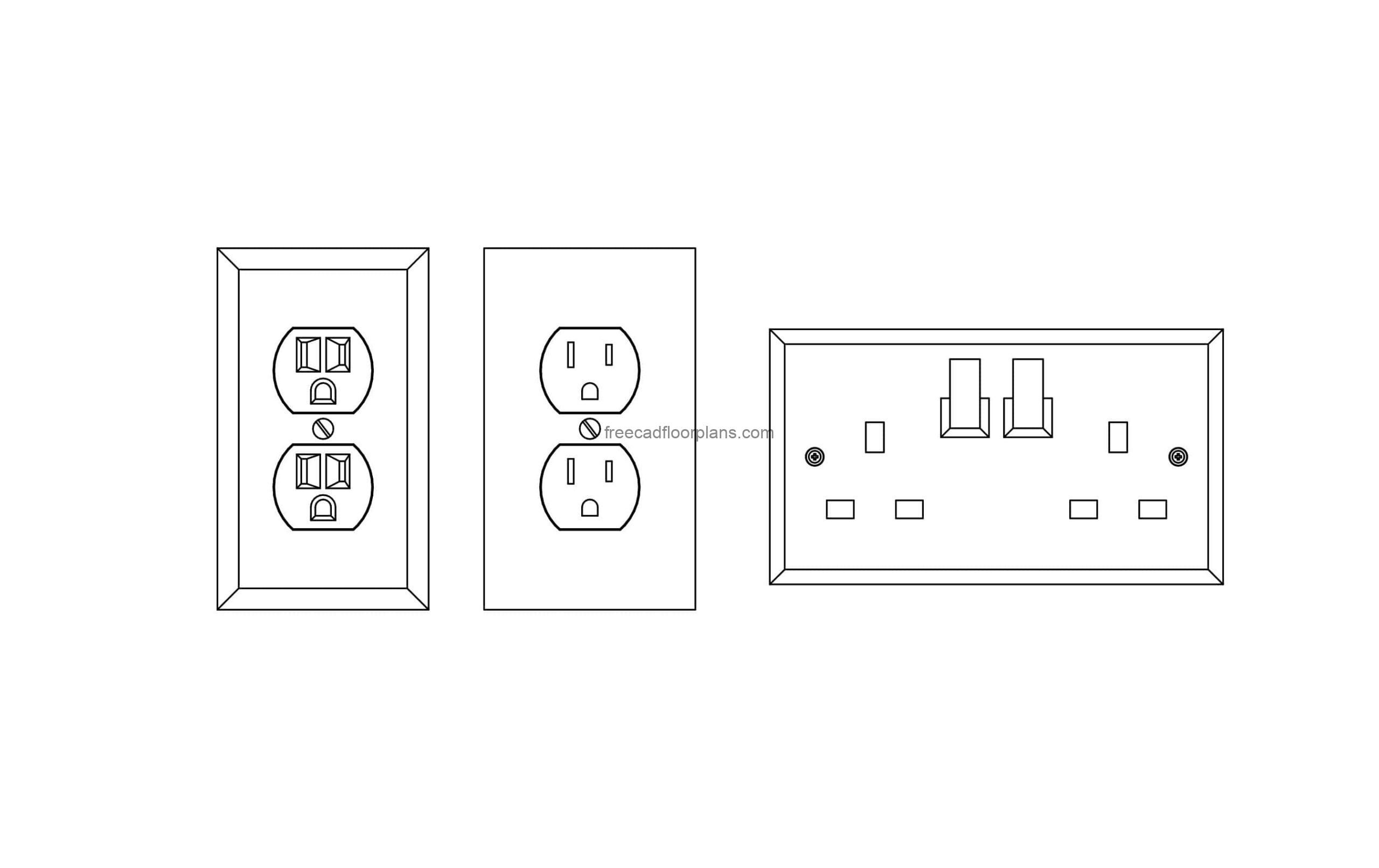
Electrical Outlet Dwg Cad
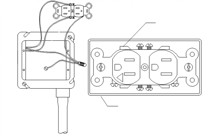
Installation of electrical outlets in a wall cad drawing 2d details dwg

how to draw outlet on electrical drawings Wiring Work
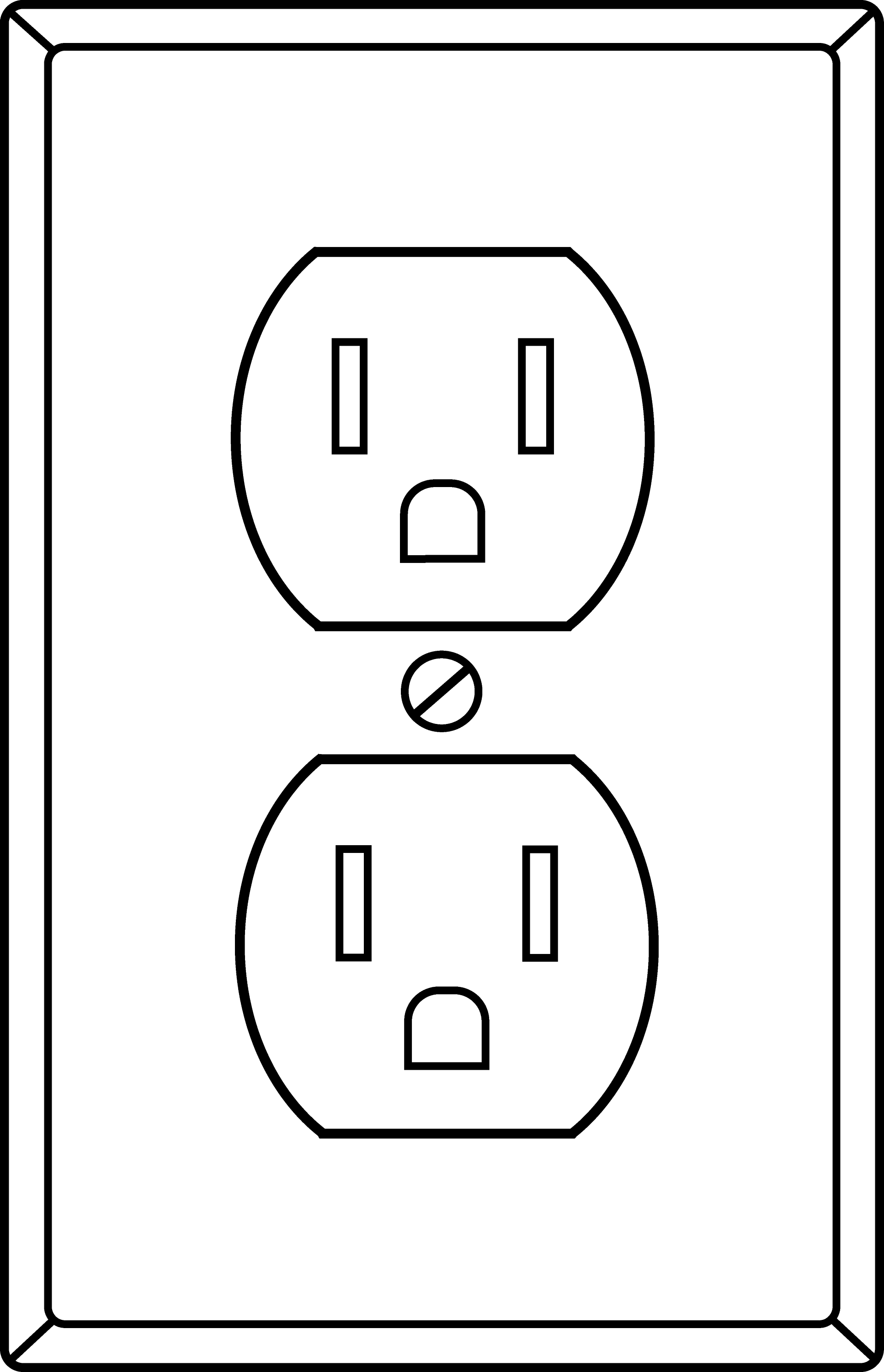
Electrical Socket Line Art Free Clip Art
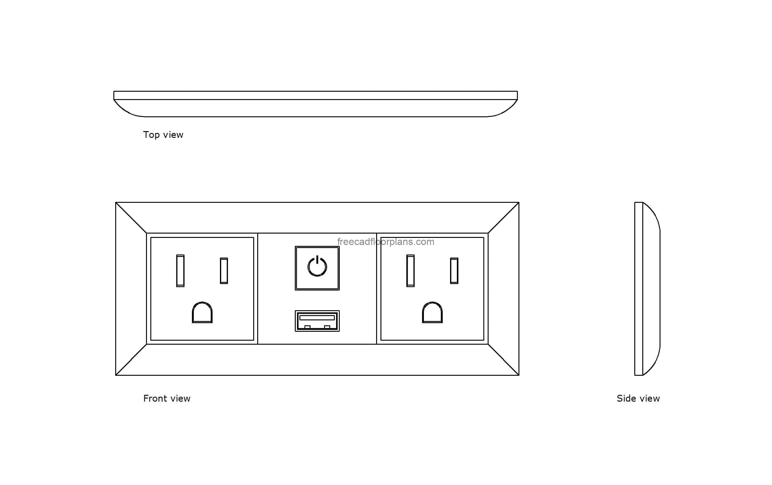
Electrical Outlet Dwg Cad
Electrical Outlet Drawing by CSA Images Fine Art America

How to Draw Electric Outlet YouTube

Installation of electrical outlets in a wall cad drawing details dwg
According To Nec, An Outlet Is The Point(S) In An Electrical Wiring System Where Current Can Be Taken And Utilize By Electrical Appliances And Equipment By Plugging Them In It.
It Also Provides Information On The Type Of Connections Used, The Voltage, And The Polarity Of The Wiring.
Chapter 4 Special Detailed Requirements Based On Occupancy And Use.
Chapter 5 General Building Heights And Areas.
Related Post: