Drawing Valve Symbols, Downloadable pdf of valve, actuator and other popular p&id symbols.
Drawing Valve Symbols - It should be noted that globe and gate valves will often be depicted by the same valve symbol. Some valves are capable of throttling flow, other valve types can Web a piping and instrumentation diagram (p&id) is a graphic representation of a process system that includes the piping, vessels, control valves, instrumentation, and other process components and equipment in the system. Valves are used to control the direction, flow rate, and pressure of fluids. Components that connect sections of piping, change the direction of flow, or enable branching, including elbows, tees, reducers, and flanges. Web • examples of the common types are the globe valve, gate valve, ball valve, plug valve, butterfly valve, diaphragm valve, check valve, pinch valve, and safety valve. These valves have multiple ports within the body of the valve. Valve symbols are graphical representations of various types of valves used in piping and instrumentation diagrams (p&ids) and other engineering schematics. Such as ball valve, plug valve, refile valve, gate valve, check valve, butterfly valve. Web isometric drawing symbols for valves. This comprehensive overview delves into the world of valve symbols, providing detailed explanations and examples to empower professionals with the. Here is a list of symbols for various types of valves used in process industry. Web these valve symbols convey essential information about the valve type, function, and operation, facilitating effective communication among engineers, designers, and technicians. These symbols are. Indicators like a vertical line might suggest a gate valve symbol or a small dark circle suggesting a globe valve symbol. Web what are valve symbols and why are they important in engineering drawings? Web with lucidchart, you can easily create clean, streamlined p&ids, then share with colleagues or classmates. Here is a list of symbols for various types of. Web here, we will focus on valve symbols, depicted typically as two lines (representing piping) connected to a boxy or triangular symbol that represents the valve’s type. These symbols are standardised to represent various valve types such as ball, gate, globe, check, and butterfly valves, each with its unique shape and design on the diagram. They include the valve symbol. A globe valve operates by a barrier, such as a plug, moving up or down to seal a stationary ring. Start a free trial and see for yourself. The valve symbols with a modifier will tell you about the exact valve type used in the pipeline. Provide a chart compiling all valves 對and locations and furnish same to owner. Web. Devices that control the flow of materials through the piping system, represented by specific symbols for gate valves, globe valves, check valves, ball valves, butterfly valves, etc. They include the valve symbol with modifier and the generic valve symbols. The valve symbols with a modifier will tell you about the exact valve type used in the pipeline. These valves have. Web • examples of the common types are the globe valve, gate valve, ball valve, plug valve, butterfly valve, diaphragm valve, check valve, pinch valve, and safety valve. Some valves are capable of throttling flow, other valve types can Start a free trial and see for yourself. Videos you watch may be added to the tv's watch history and influence. Valve symbols are graphical representations of various types of valves used in piping and instrumentation diagrams (p&ids) and other engineering schematics. Provide brass valve tags & chains for t\ൈe purpose of identification. Web what are valve symbols and why are they important in engineering drawings? Web provide provide valves of the type and size as indicated on the drawings and. • each type of valve has been designed to meet specific needs. Valves are used to control the direction, flow rate, and pressure of fluids. The system then uses air pressure to control the opening and closing of the different valves. Web understanding these symbols is vital for professionals in the field, facilitating effective communication and accurate representation of valve. Figure 1 shows the symbols that depict the major valve types. Web with lucidchart, you can easily create clean, streamlined p&ids, then share with colleagues or classmates. Figure 1 shows the symbols that depict the major valve types. Web the type of valve symbol in a p&id is indicative of its specific function and operation within the process system. These. Such as ball valve, plug valve, refile valve, gate valve, check valve, butterfly valve. Web to signify this precise valve on a diagram, the bowtie symbol is used with a downward pointing arrow in the center. This comprehensive overview delves into the world of valve symbols, providing detailed explanations and examples to empower professionals with the. Similarly, this symbol shows. • each type of valve has been designed to meet specific needs. Pneumatic valve types and symbols. Valve symbols are graphical representations of various types of valves used in piping and instrumentation diagrams (p&ids) and other engineering schematics. Web here, we will focus on valve symbols, depicted typically as two lines (representing piping) connected to a boxy or triangular symbol that represents the valve’s type. Web with lucidchart, you can easily create clean, streamlined p&ids, then share with colleagues or classmates. Such as ball valve, plug valve, refile valve, gate valve, check valve, butterfly valve. Figure 1 shows the symbols that depict the major valve types. Sign up for free and use lucidchart's p&id shape library! It streamlines collaboration among engineers, ensuring everyone interprets system designs consistently. In such cases, information concerning the valve type may be conveyed by the component Provide brass valve tags & chains for t\ൈe purpose of identification. Web isometric drawing symbols for valves. Start a free trial and see for yourself. To avoid this, cancel and sign in to youtube on your computer. Web these valve symbols convey essential information about the valve type, function, and operation, facilitating effective communication among engineers, designers, and technicians. Web • examples of the common types are the globe valve, gate valve, ball valve, plug valve, butterfly valve, diaphragm valve, check valve, pinch valve, and safety valve.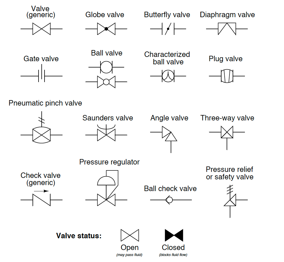
Flow Control Valve Schematic Symbol
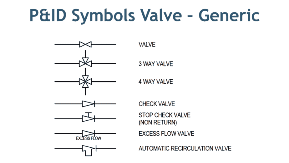
Símbolos de válvulas en P&ID Válvula de bola, válvula de alivio y más
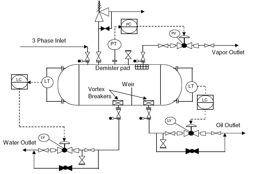
P&ID Valve Symbols How to read them on most XHVAL
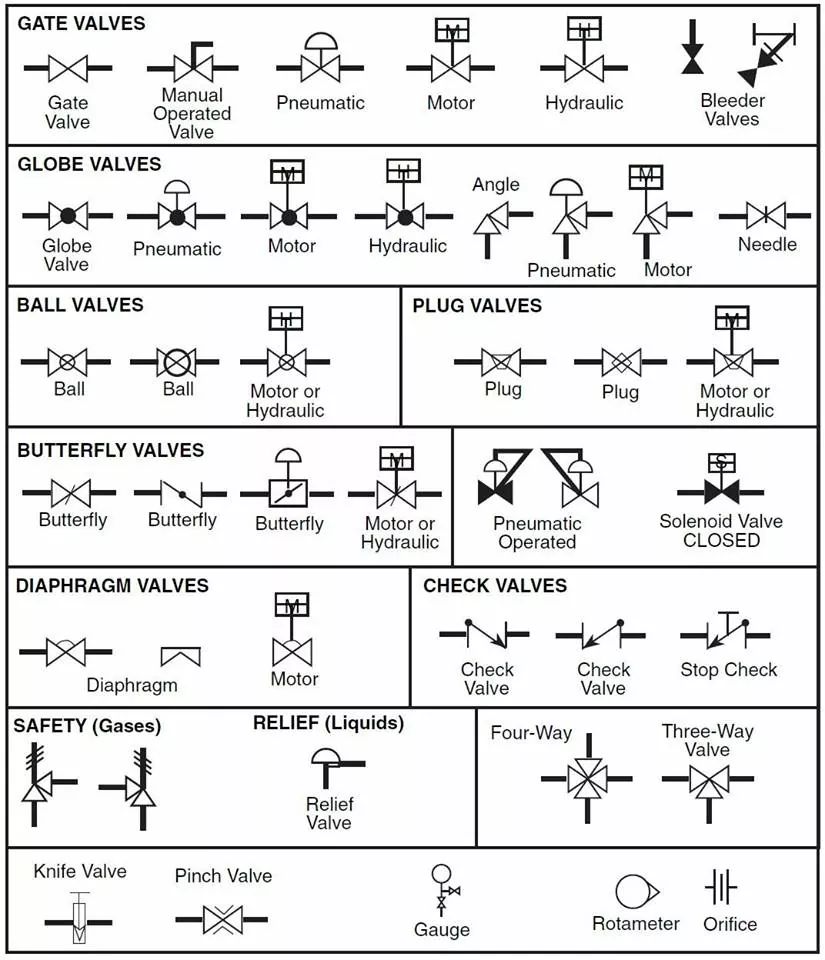
Valve Symbols for P&IDs The Engineering Concepts

How to Drawing Valve Symbols 1 YouTube
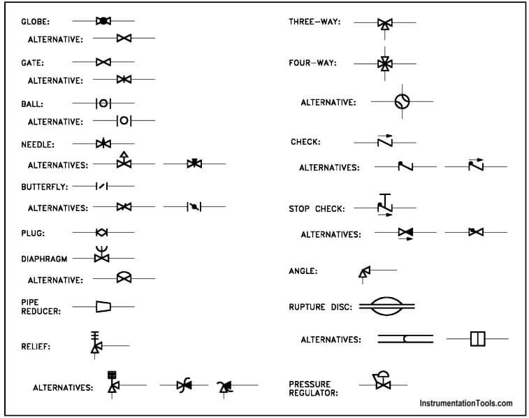
Piping and Instrumentation Symbols Instrumentation Tools
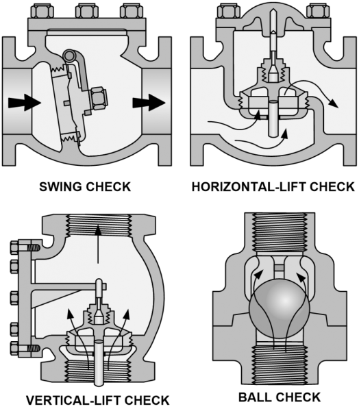
Valve Symbols Understanding how to read FDs and P&IDs
![How to Read P&ID Component & Valve Symbols [w/ Download]](https://www.geminivalve.com/wp-content/uploads/2020/07/Valve-Symbols-2-way-valve@2x-100.jpg)
How to Read P&ID Component & Valve Symbols [w/ Download]
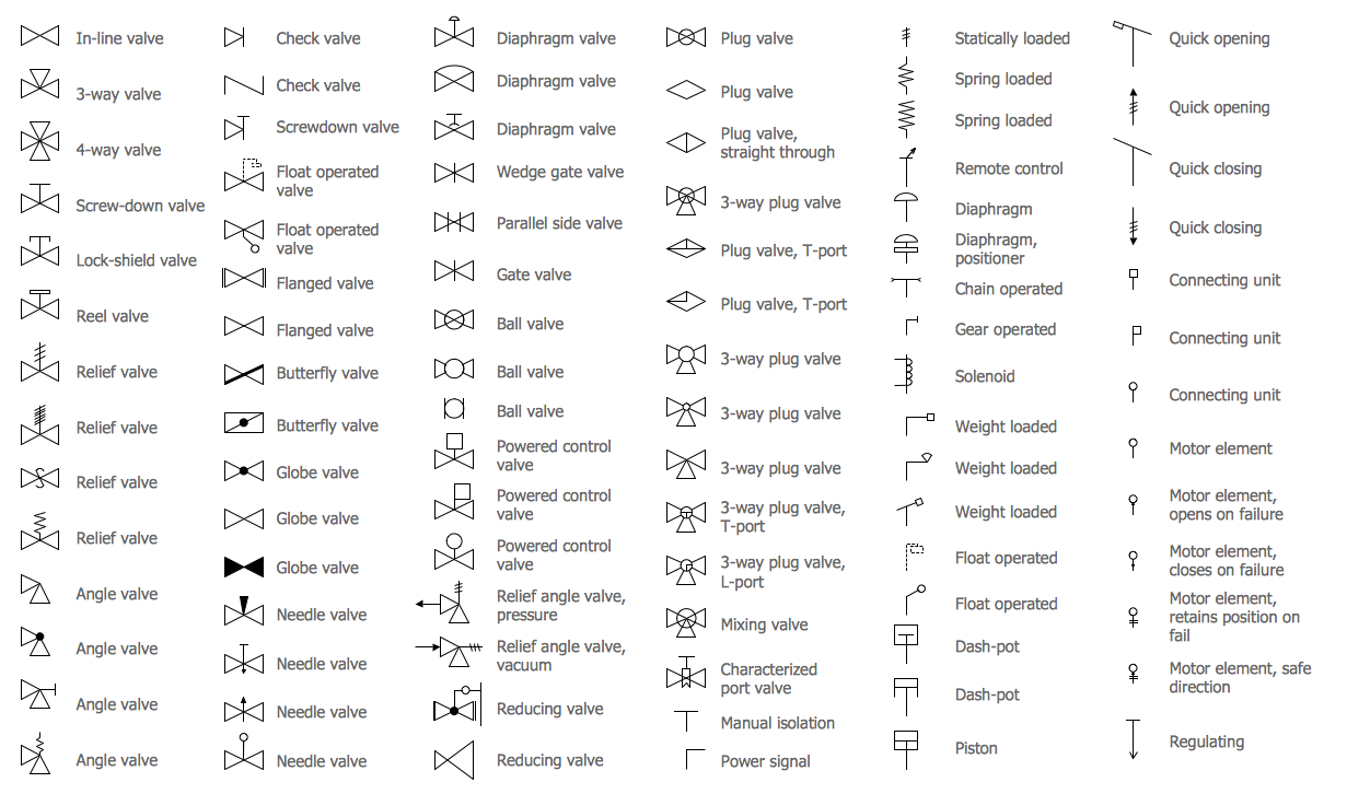
Valves Symbols Rooter Hero University

Control Valve 5/3 Valve Pneumatic Symbols CAD Block And Typical
In This Article, We Will Identify The Most Commonly Used Control Valve Symbols.
Web Valve Symbols Valves Are Used To Control The Direction, Flow Rate, And Pressure Of Fluids.
The Common P&Id Symbols Are Listed Here:
Devices That Control The Flow Of Materials Through The Piping System, Represented By Specific Symbols For Gate Valves, Globe Valves, Check Valves, Ball Valves, Butterfly Valves, Etc.
Related Post: