Drawing Symbols For Piping, P&ids are one of the most important documents for any project and are crucial in all stages of process system development and operation.
Drawing Symbols For Piping - The symbols that represent fittings, valves and flanges are modified to adapt to the isometric grid. This symbol represents a section of pipe that is straight and does not have any bends or curves. Pressure, temperature, flow, level, switches, alarms, and miscellaneous. Pipe routing, length, and coordinates. Web piping and instrumentation diagrams (p&ids) are articulate drawings of a processing plan with various symbols and abbreviations that entail the piping and process equipment with its instrumentation and control machinery. Web the graphical representation in a p&id drawing establishes the functional relationship of piping, instrumentation, and mechanical equipment. 5 provides symbols for fans, pumps, and turbines. Pressure, temperature, flow, level, switches, alarms, and miscellaneous. 1977 scope this part of bs 1553 specifies graphical symbols for use in flow and piping diagrams for process plant. Web unlike orthographics, piping isometrics allow the pipe to be drawn in a manner by which the length, width and depth are shown in a single view. These symbols are categorized under the following headings: Typical examples for p&i drawings: Pressure, temperature, flow, level, switches, alarms, and miscellaneous. Equipment, piping, vessels, heat exchangers, pumps, instruments, and valves. 1 normal ave montclair, nj 07043 heating & ventilating unit #3 replacement panzer gymnasium msu project no. These tools generate the 3d representation of the piping layout, including pipe dimensions, fittings, valves, and other components. Web piping and instrumentation diagrams (p&ids) are articulate drawings of a processing plan with various symbols and abbreviations that entail the piping and process equipment with its instrumentation and control machinery. This symbol represents a section of pipe that is straight and. Web piping isometric drawing software is an essential tool for piping engineers and designers to create detailed isometric drawings of piping systems. Piping fabrication work is based on isometric drawings. Web build your custom piping and instrumentation diagrams with professional symbols for motors, flow meters, segmented pipes, pumps, tanks, valves, sensors, process cooling, process heating, water and wastewater systems, and. Llcjohnson & urban,c o n s u l t i n g e n g i n e e r s. Web unlike orthographics, piping isometrics allow the pipe to be drawn in a manner by which the length, width and depth are shown in a single view. Web mechanical symbols for isometric drawings. Spacing or centreline distance between one. Correct positioning of the piping assembly on the pipe rack. Web the shapes in this legend are representative of the functional relationship between piping, instrumentation, and system equipment units. 1977 scope this part of bs 1553 specifies graphical symbols for use in flow and piping diagrams for process plant. In other words, p&ids are schematics or diagrams that lay out. 5 provides symbols for fans, pumps, and turbines. Lighter lines show connected pipe, and are not parts of the symbols. Pipe routing, length, and coordinates. The drawing axes of the isometrics intersect at an angle of 60°. Pressure, temperature, flow, level, switches, alarms, and miscellaneous. Pressure, temperature, flow, level, switches, alarms, and miscellaneous. The symbols that represent fittings, valves and flanges are modified to adapt to the isometric grid. These symbols are categorized under the following headings: Isometrics are usually drawn from information found on a plan and elevation views. Web there are a variety of piping symbols used in metal fabrication drawings, including: Pressure, temperature, flow, level, switches, alarms, and miscellaneous. Web various symbols are used to indicate piping components, instrumentation, equipments in engineering drawings such as piping and instrumentation diagram (p&id), isometric drawings, plot plan, equipment layout, welding drawings etc. Web build your custom piping and instrumentation diagrams with professional symbols for motors, flow meters, segmented pipes, pumps, tanks, valves, sensors, process. 5 provides symbols for fans, pumps, and turbines. Correct positioning of the piping assembly on the pipe rack. Web mechanical symbols for isometric drawings. The symbols that represent fittings, valves and flanges are modified to adapt to the isometric grid. Piping isometric drawing software is an essential tool for piping engineers and designers to create detailed isometric drawings of piping. It is the most important deliverable of piping engineering department. With lucidchart, it's easy to access all of the featured p&id symbols. 1977 scope this part of bs 1553 specifies graphical symbols for use in flow and piping diagrams for process plant. These symbols are categorized under the following headings: The symbols that represent fittings, valves and flanges are modified. 2.5 figure 5 provides symbols for. Pipe routing, length, and coordinates. These symbols are categorized under the following headings: Correct positioning of the piping assembly on the pipe rack. Typical examples for p&i drawings: It is the most important deliverable of piping engineering department. With lucidchart, it's easy to access all of the featured p&id symbols. Isometrics are usually drawn from information found on a plan and elevation views. Pressure, temperature, flow, level, switches, alarms, and miscellaneous. Spacing or centreline distance between one pipe to the other line. Pressure, temperature, flow, level, switches, alarms, and miscellaneous. 1977 scope this part of bs 1553 specifies graphical symbols for use in flow and piping diagrams for process plant. This symbol represents a curved section of pipe used to change the direction of the flow. Lighter lines show connected pipe, and are not parts of the symbols. Symbols have been based generally on the philosophy described in the isa s5.1 standard. Pressure, temperature, flow, level, switches, alarms, and miscellaneous.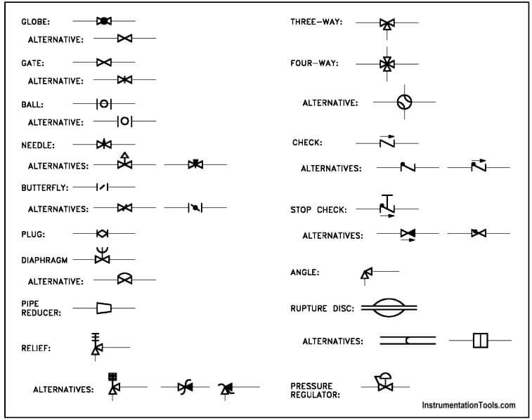
Piping and Instrumentation Symbols Instrumentation Tools

Piping Diagram Symbols Valves
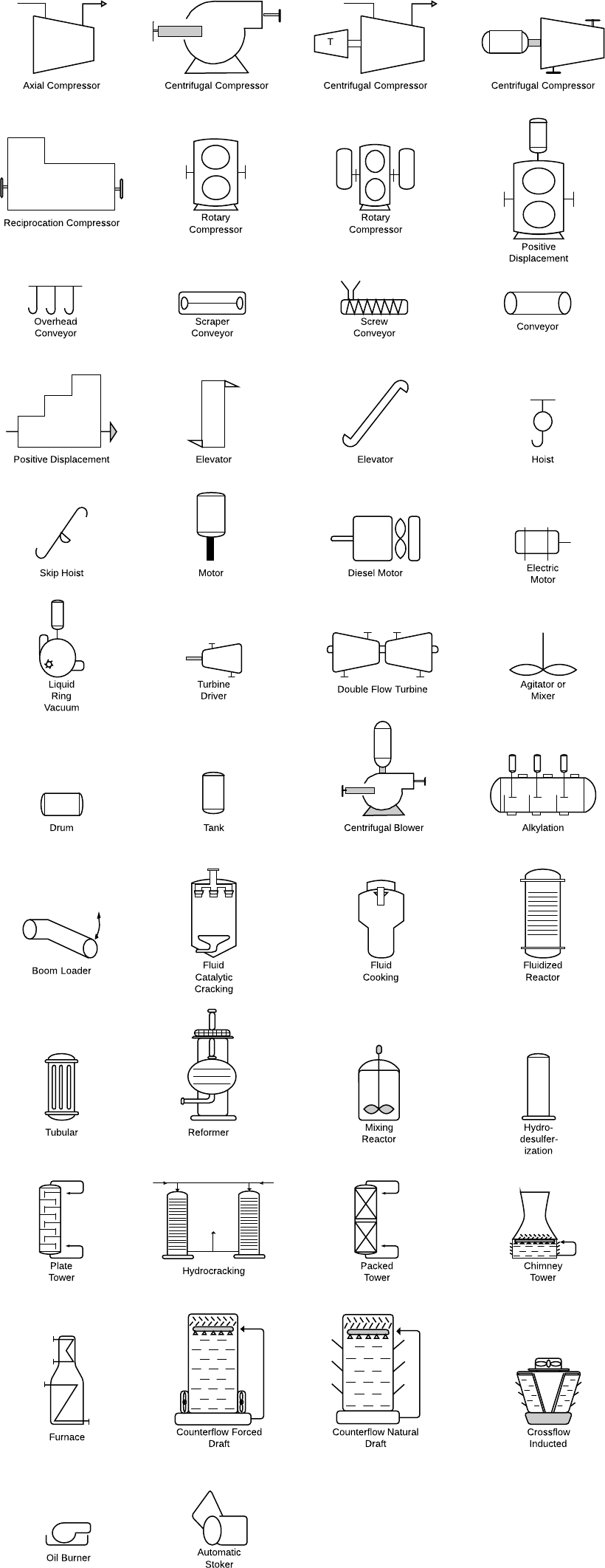
Piping Isometric Drawing Symbols Pdf at Explore
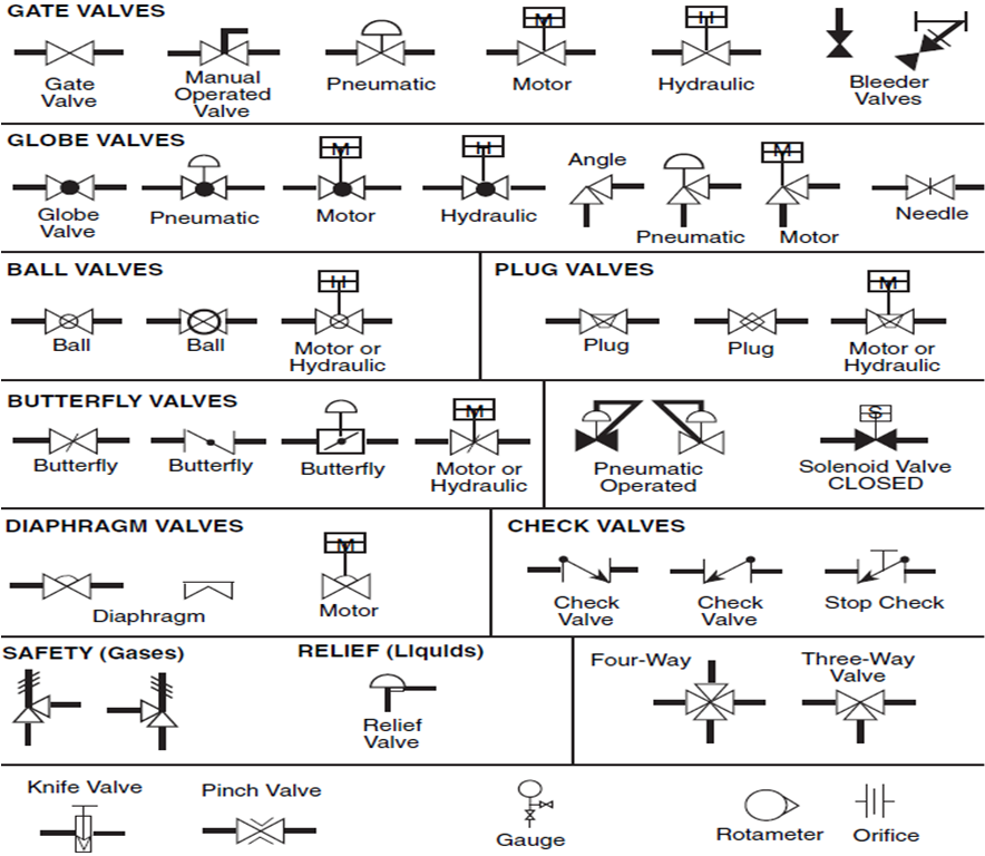
Piping Schematic Valve Symbols
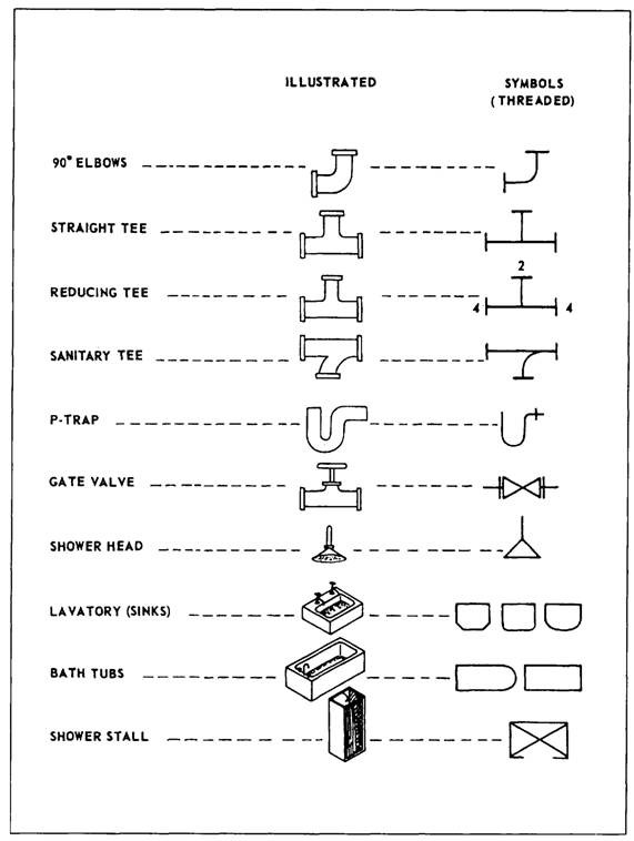
Piping Isometric Drawing Symbols Pdf at Explore
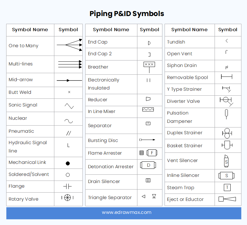
What is a P&ID Beginner’s Guide EdrawMax Online
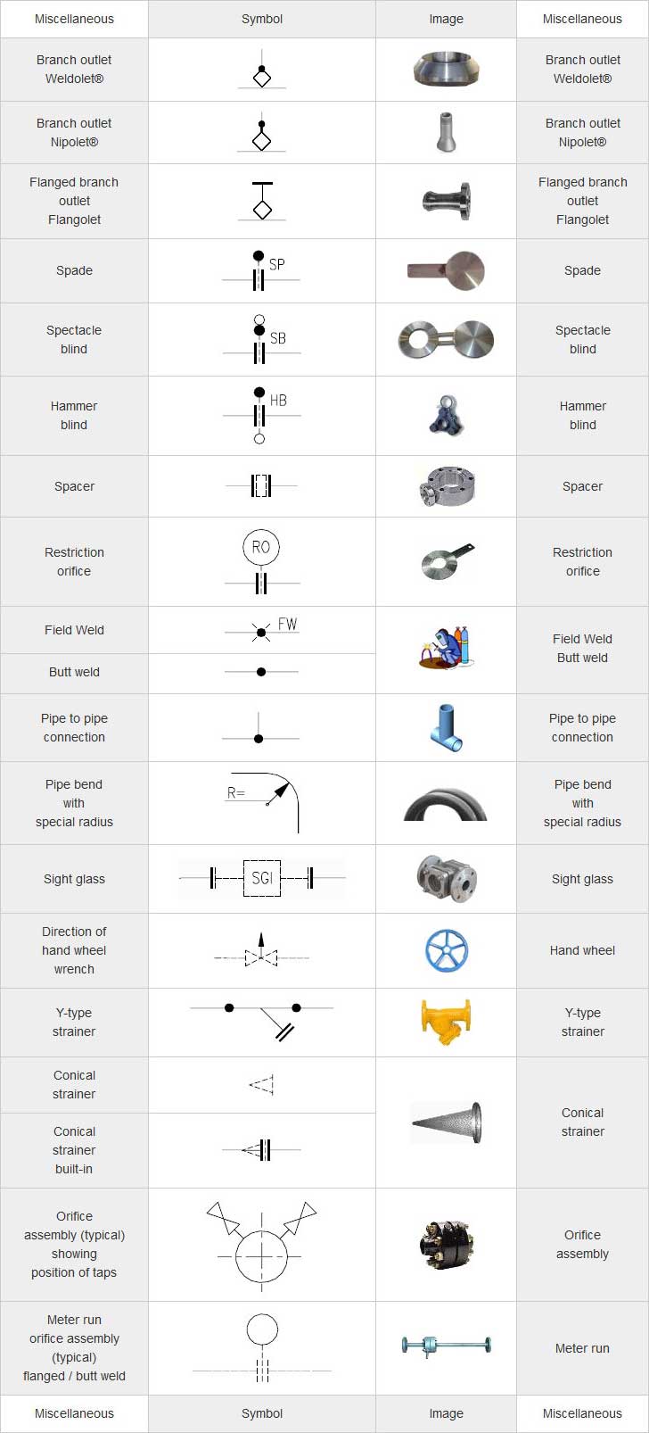
Piping Coordination System Mechanical symbols for Isometric drawings

What is Piping Isometric drawing? How to Read Piping Drawing? ALL
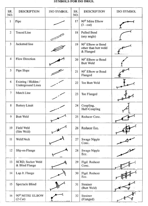
Piping Isometric Drawings The Piping Engineering World
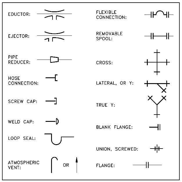
Piping Schematic Symbols
Checkout List Of Such Symbols Given Below.
These Tools Generate The 3D Representation Of The Piping Layout, Including Pipe Dimensions, Fittings, Valves, And Other Components.
Piping Fabrication Work Is Based On Isometric Drawings.
Web Symbols For Piping & Instrumentation Drawings.
Related Post: