Draw The Shear And Bending Moment Diagrams For The Beam, Web the course covers shear force and bending moment diagram review, method of superposition, moment area method, force method, displacement method, slope deflection method, and 3 moment.
Draw The Shear And Bending Moment Diagrams For The Beam - 20 kn 40 kn/m cl 150 kn m 8 m 3 m prob. There is a long way and a quick way to do them. Then, starting from one end of the beam, the shear force and bending moment at each section can be calculated using equations of. Web the shear diagram will plot out the internal shearing forces within a beam, or other body that is supporting multiple forces perpendicular to the length of the beam or body itself. There are 3 steps to solve this one. The reactions shown on the diagram are determined from equilibrium equations as follows: Loading tends to cause failure in two main ways: Web write equations for the shear v and bending moment m for any section of the beam in the interval ab. Web in this post we’ll give you a thorough introduction to shear forces, bending moments and how to draw shear and moment diagrams with worked examples. Web to draw shear and bending moment diagrams for simple beams, the first step is to determine the reactions at the supports. Web shear force and bending moment diagrams are powerful graphical methods that are used to analyze a beam under loading. Skyciv beam tool guides users along a professional beam calculation workflow, culminating in the ability to view and determine if they comply with your region's design codes. − 6 × 9 1. • evaluate all support reactions draw the shear. A shear force diagram can be constructed from the loading diagram of the beam. • evaluate all support reactions draw the shear diagram (with values) draw the moment diagram (with values) sketch the deflected shape additional solution requirements: Web the course covers shear force and bending moment diagram review, method of superposition, moment area method, force method, displacement method, slope. − 6 × 9 1. There are 3 steps to solve this one. • consider [by] as the redundant. Shear and bending moment equations. The beginning, end, or change of a. Web in this post we’ll give you a thorough introduction to shear forces, bending moments and how to draw shear and moment diagrams with worked examples. • evaluate all support reactions draw the shear diagram (with values) draw the moment diagram (with values) sketch the deflected shape additional solution requirements: 20 kn 40 kn/m cl 150 kn m 8 m. Web the shear diagram will plot out the internal shearing forces within a beam, or other body that is supporting multiple forces perpendicular to the length of the beam or body itself. Web being able to draw shear force diagrams (sfd) and bending moment diagrams (bmd) is a critical skill for any student studying statics, mechanics of materials, or structural. Draw a fbd of the structure Consider a sign convention of downward positive. Shear and bending moment diagrams. Web this video explains how to draw shear force diagram and bending moment diagram with easy steps for a simply supported beam loaded with a concentrated load. There is a long way and a quick way to do them. Web shear force and bending moment diagrams are powerful graphical methods that are used to analyze a beam under loading. 20 kn 40 kn/m cl 150 kn m 8 m 3 m prob. Skyciv beam tool guides users along a professional beam calculation workflow, culminating in the ability to view and determine if they comply with your region's design codes.. Draw a fbd of the structure After you have the diagrams, answer the questions. The reactions shown on the diagram are determined from equilibrium equations as follows: Web calculate the reactions at the supports of a beam, frame and truss. In order to draw this, first the reactions must be determined always. Web being able to draw shear force diagrams (sfd) and bending moment diagrams (bmd) is a critical skill for any student studying statics, mechanics of materials, or structural engineering. After you have the diagrams, answer the questions. A shear force diagram can be constructed from the loading diagram of the beam. Web shear force and bending moment diagrams are powerful. • evaluate all support reactions draw the shear diagram (with values) draw the moment diagram (with values) sketch the deflected shape additional solution requirements: Loading tends to cause failure in two main ways: Web to draw shear and bending moment diagrams for simple beams, the first step is to determine the reactions at the supports. 5 lb 12 lb 5. Web our calculator generates the reactions, shear force diagrams (sfd), bending moment diagrams (bmd), deflection, and stress of a cantilever beam or simply supported beam. Figures 1 through 32 provide a series of shear and moment diagrams with accompanying formulas for design of beams under various static loading conditions. Draw the shear and moment diagrams for the beam. • consider [by] as the redundant. Web the shear diagram will plot out the internal shearing forces within a beam, or other body that is supporting multiple forces perpendicular to the length of the beam or body itself. This beam calculator is designed to help you calculate and plot the bending moment diagram (bmd), shear force diagram (sfd), axial force diagram. Then the vertical components of forces and reactions are successively summed from the left end of They allow us to see where the maximum loads occur so that we can optimize the design to prevent failures and reduce the overall weight and cost of the structure. This page will walk you through what shear forces and bending moments are, why they are useful, the procedure for drawing the diagrams and some other keys aspects as well. Web construction of shear force and bending moment diagrams: The shear and moment diagrams are both used primarily in the analysis of horizontal beams in structures, such as floor joists, ceiling joists, and other horizontal. David roylance department of materials science and engineering massachusetts institute of technology cambridge, ma 02139 november 15, 2000. Shear and bending moment equations. The reactions shown on the diagram are determined from equilibrium equations as follows: Consider a sign convention of downward positive. 20 kn 40 kn/m cl 150 kn m 8 m 3 m prob.
Shear and moment diagram Bending moment, Civil engineering design
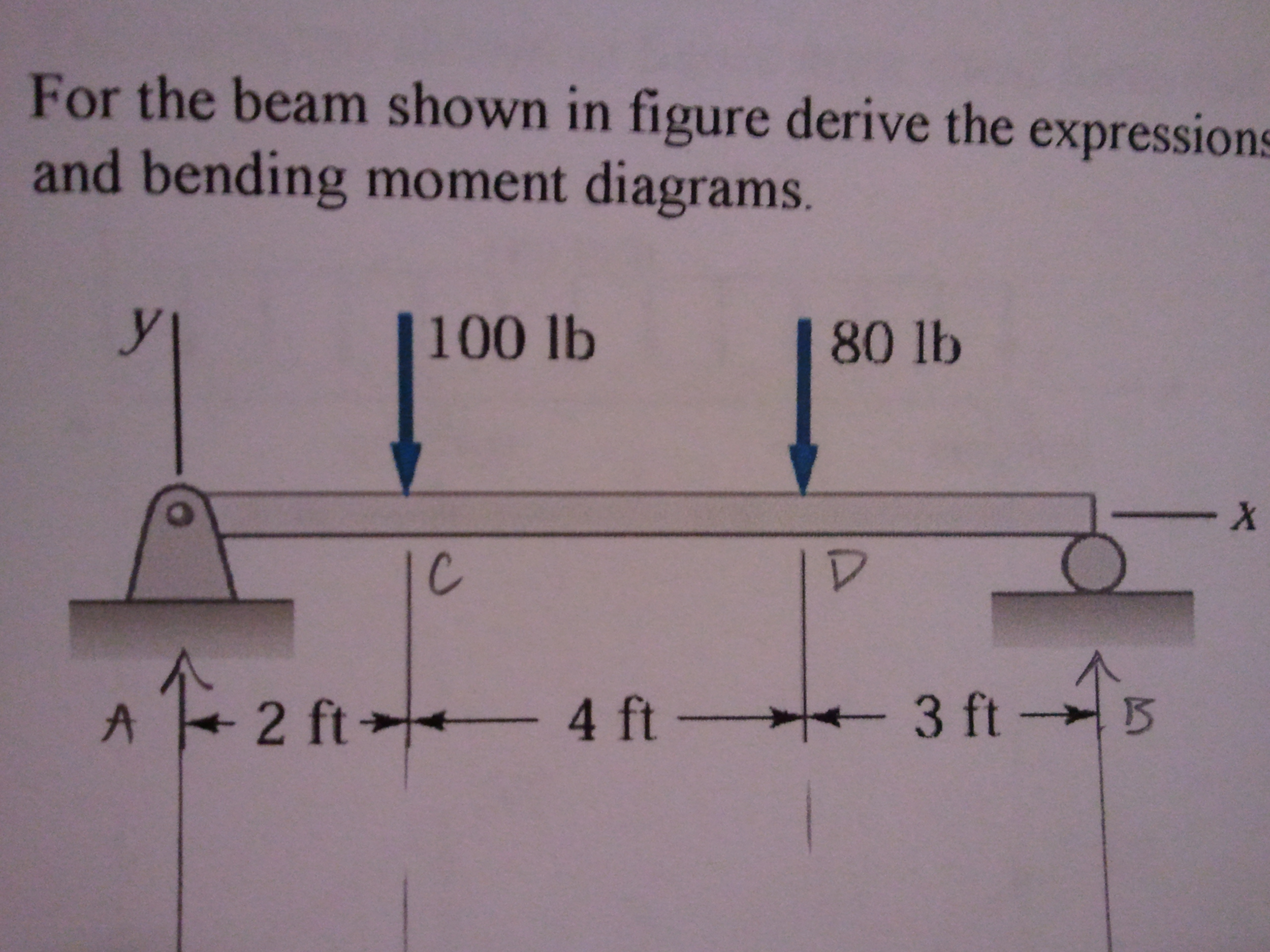
Draw Shear Force And Bending Moment Diagrams For T...
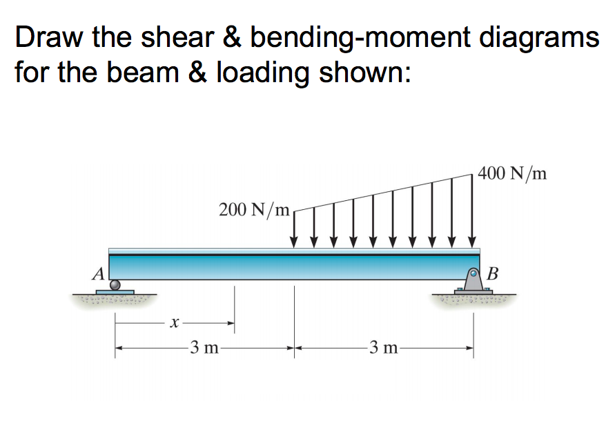
Solved Draw the shear & bendingmoment diagrams for the beam
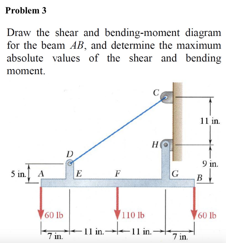
Solved Draw the shear and bending moment for the beam AB,
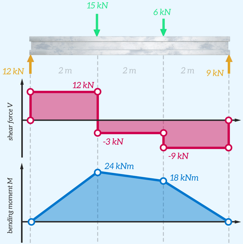
Understanding Shear Force and Bending Moment Diagrams The Efficient

Solved Draw the shear and moment diagrams for the beam.
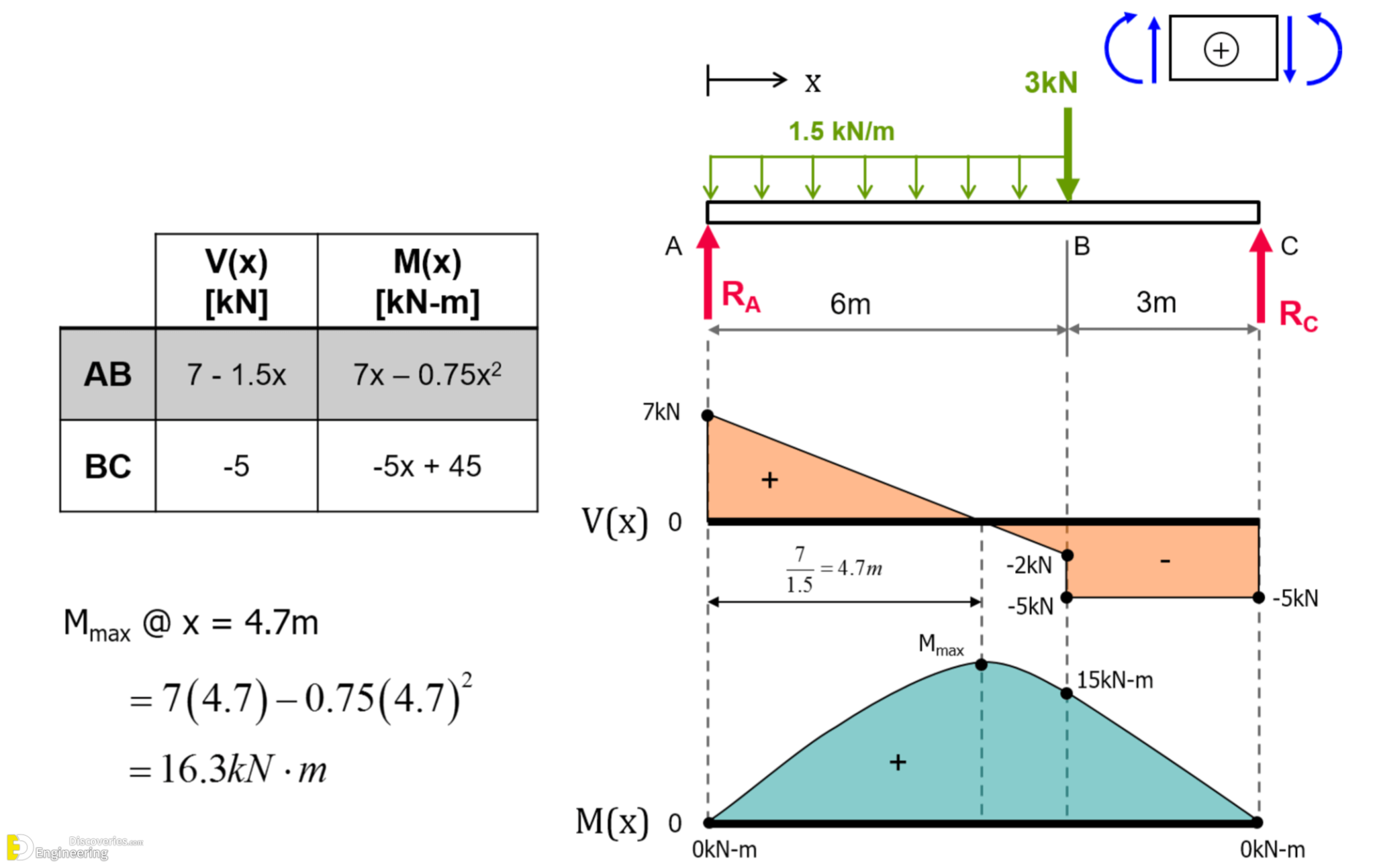
Learn How To Draw Shear Force And Bending Moment Diagrams Engineering
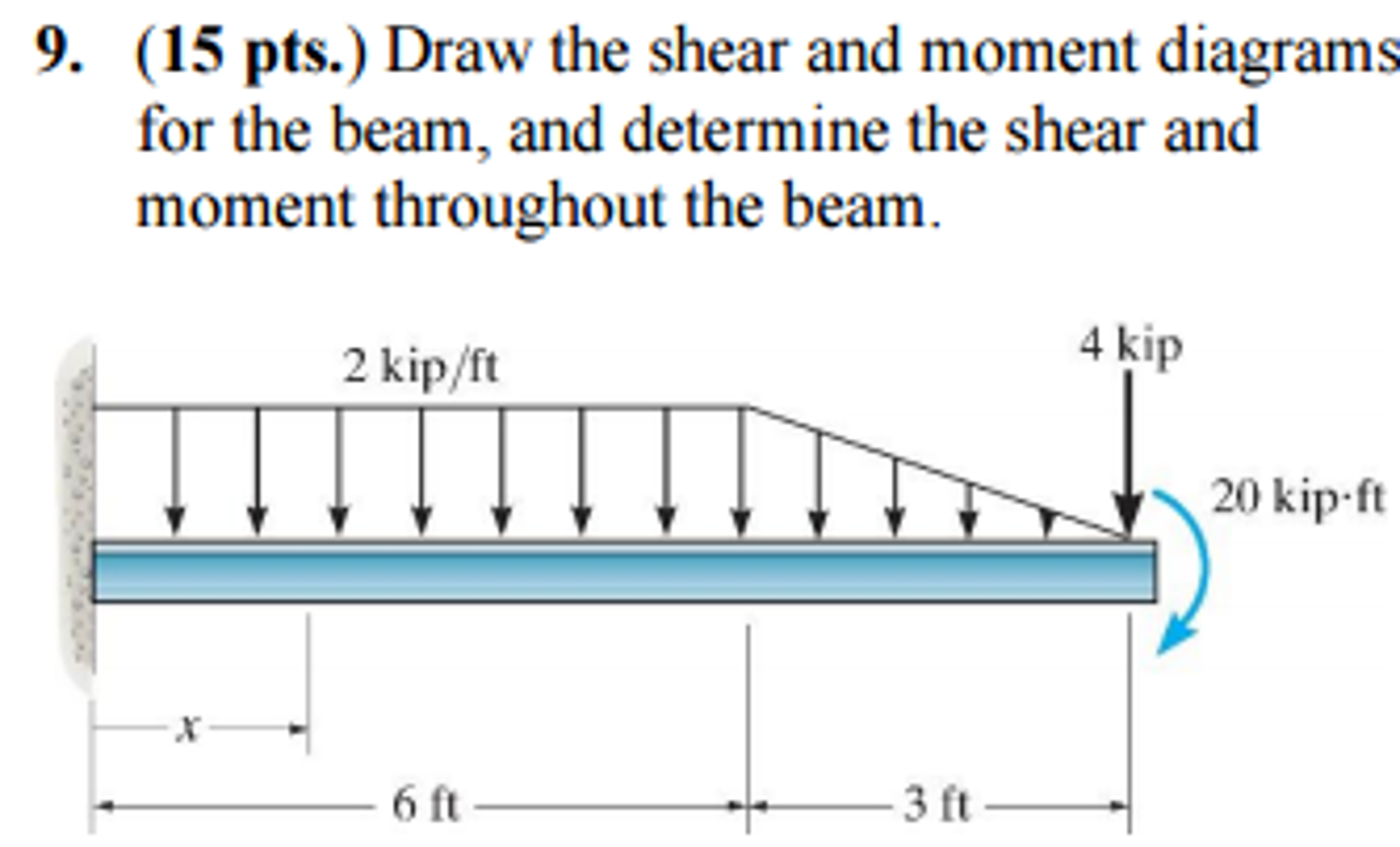
Draw Shear And Moment Diagrams For The Beam

Shear force and bending moment diagrams for a simply supported beam

Bending moment and shear force diagram of a cantilever beam
Shear And Bending Moment Diagrams.
The Beginning, End, Or Change Of A.
Web This Video Explains How To Draw Shear Force Diagram And Bending Moment Diagram With Easy Steps For A Simply Supported Beam Loaded With A Concentrated Load.
Skyciv Beam Tool Guides Users Along A Professional Beam Calculation Workflow, Culminating In The Ability To View And Determine If They Comply With Your Region's Design Codes.
Related Post: