Draw Shear Moment Diagrams, Draw a fbd of the structure.
Draw Shear Moment Diagrams - This is a very useful skill to be good at for statics and mechanics of materials. Web being able to draw shear force diagrams (sfd) and bending moment diagrams (bmd) is a critical skill for any student studying statics, mechanics of materials, or structural engineering. Draw a fbd of the structure. Lined up below the shear diagram, draw a set of axes. A moment diagram is drawn below the shear diagram to the same scale. Web draw the shear force and bending moment diagrams for the cantilever beam supporting a concentrated load of 5 lb at the free end 3 ft from the wall. Web figures 1 through 32 provide a series of shear and moment diagrams with accompanying formulas for design of beams under various static loading conditions. Web understanding shear force and bending moment diagrams. Web axial, shear, and bending moment diagrams (afd, sfd, and bmd) show the internal forces and moments along a structural member. Web shear force and bending moment diagrams are analytical tools used in conjunction with structural analysis to help perform structural design by determining the value of shear forces and bending moments at a given point of a structural element such as a beam. This example deals with a constant distributed force (shear is a linear function of x). Shear and moment diagrams and formulas are excerpted from the western woods use book, 4th edition, and are provided herein as a courtesy of western wood products association. We have learned how to construct a moment diagram from either writing the moment as a function. They help determine the material, size, and type of a member given a set of loads it. Web to create the moment diagram for a shaft, we will use the following process. Web figures 1 through 32 provide a series of shear and moment diagrams with accompanying formulas for design of beams under various static loading conditions. Web shear and. Write equations for the shear v and bending moment m for any section of the beam in the interval ab. This is a very useful skill to be good at for statics and mechanics of materials. Shear and moment diagrams and formulas are excerpted from the western woods use book, 4th edition, and are provided herein as a courtesy of. Web in this video we cover how to draw the shear and moment diagrams for a beam. Solve for all external forces and moments, create a free body diagram, and create the shear diagram. Web to create the moment diagram for a shaft, we will use the following process. By bending the beam to an excessive amount. Study slides 11. This example deals with a constant distributed force (shear is a linear function of x). Skyciv beam tool guides users along a professional beam calculation workflow, culminating in the ability to view and determine if they comply with your region's design codes. Web to create the moment diagram for a shaft, we will use the following process. Web shear force. Bending moment diagram (bmd) shear force diagram (sfd) axial force diagram (afd) frame calculator. Calculate support reactions and internal forces. There is a long way and a quick way to do them. Calculate the reactions using the equilibrium equations (may not need to do this if choosing a cantilever beam and using the free side for the fbd). Web learn. Web to create the moment diagram for a shaft, we will use the following process. Web figures 1 through 32 provide a series of shear and moment diagrams with accompanying formulas for design of beams under various static loading conditions. Web to create the moment diagram for a shaft, we will use the following process. This page will walk you. Web shear and moment diagrams are graphs which show the internal shear and bending moment plotted along the length of the beam. This page will walk you through what shear forces and bending moments are, why they are useful, the procedure for drawing the diagrams and some other keys aspects as well. Lined up below the shear diagram, draw a. Web in this post we’ll give you a thorough introduction to shear forces, bending moments and how to draw shear and moment diagrams with worked examples. Calculate support reactions and internal forces. Web understanding shear force and bending moment diagrams. Shear and moment diagrams and formulas are excerpted from the western woods use book, 4th edition, and are provided herein. Shear and moment diagrams and formulas are excerpted from the western woods use book, 4th edition, and are provided herein as a courtesy of western wood products association. Calculate the reactions using the equilibrium equations (may not need to do this if choosing a cantilever beam and using the free side for the fbd). Web being able to draw shear. Web this is how we will construct shear and moment diagrams. They help determine the material, size, and type of a member given a set of loads it. Web figures 1 through 32 provide a series of shear and moment diagrams with accompanying formulas for design of beams under various static loading conditions. Web understanding shear force and bending moment diagrams. Calculate the reactions using the equilibrium equations (may not need to do this if choosing a cantilever beam and using the free side for the fbd). Web in this post we’ll give you a thorough introduction to shear forces, bending moments and how to draw shear and moment diagrams with worked examples. Draw a fbd of the structure. Web axial, shear, and bending moment diagrams (afd, sfd, and bmd) show the internal forces and moments along a structural member. Draw the shear and moment diagrams for the following frame: Solve for all external forces and moments, create a free body diagram, and create the shear diagram. This page will walk you through what shear forces and bending moments are, why they are useful, the procedure for drawing the diagrams and some other keys aspects as well. Lined up below the shear diagram, draw a set of axes. This is example shows how to use the steps outlined in the steps tab to draw shear force and bending moment diagrams. Web shear force and bending moment diagrams are analytical tools used in conjunction with structural analysis to help perform structural design by determining the value of shear forces and bending moments at a given point of a structural element such as a beam. Lined up below the shear diagram, draw a set of axes. Web draw the shear force and bending moment diagrams for the cantilever beam supporting a concentrated load of 5 lb at the free end 3 ft from the wall.
How to draw shear and moment diagrams YouTube
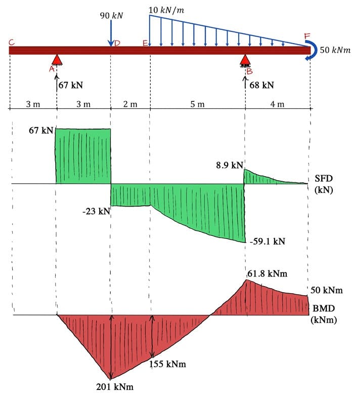
The Ultimate Guide to Shear and Moment Diagrams
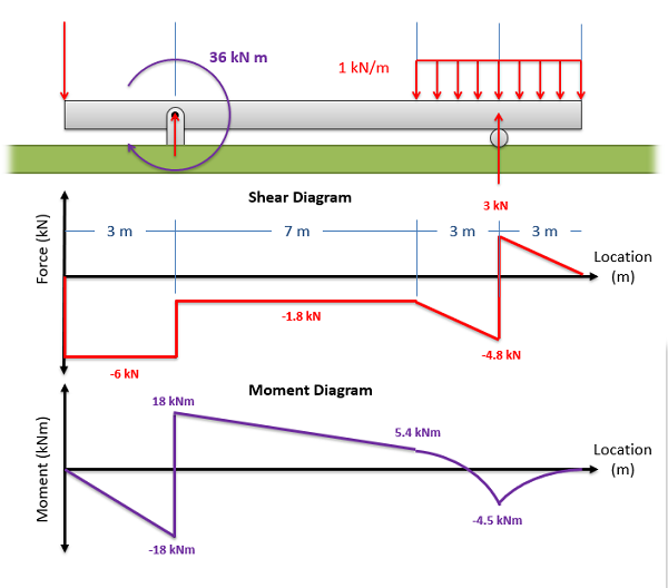
Mechanics Map Shear and Moment Diagrams

Solved Draw the shear and moment diagrams for the beam
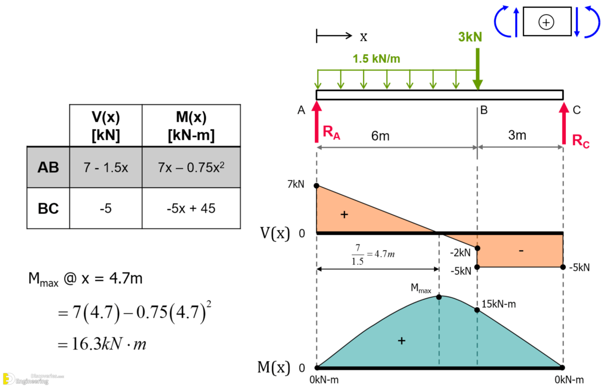
Learn How To Draw Shear Force And Bending Moment Diagrams Engineering
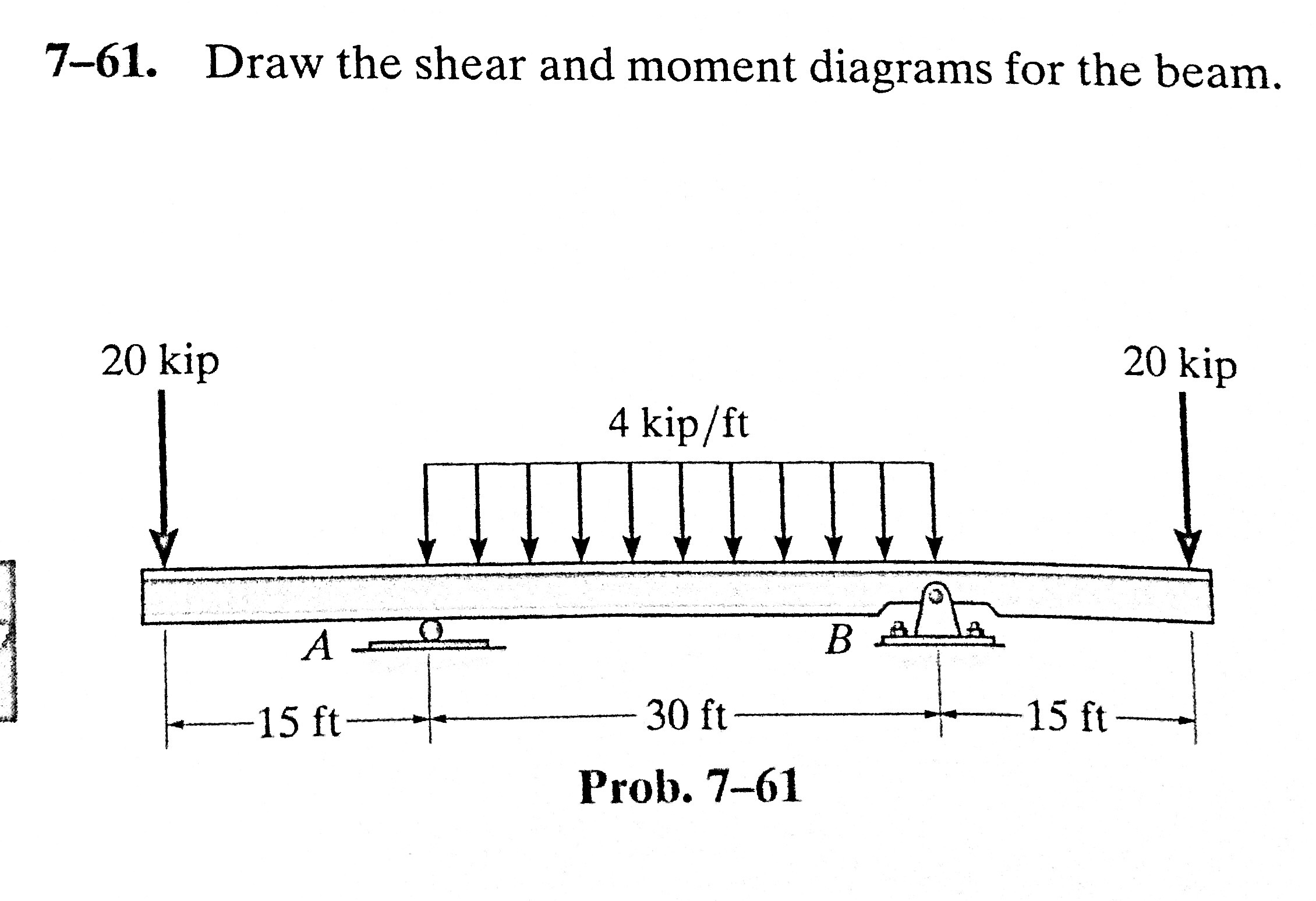
Solved 761. Draw the shear and moment diagrams for the

Draw Shear And Moment Body Diagrams
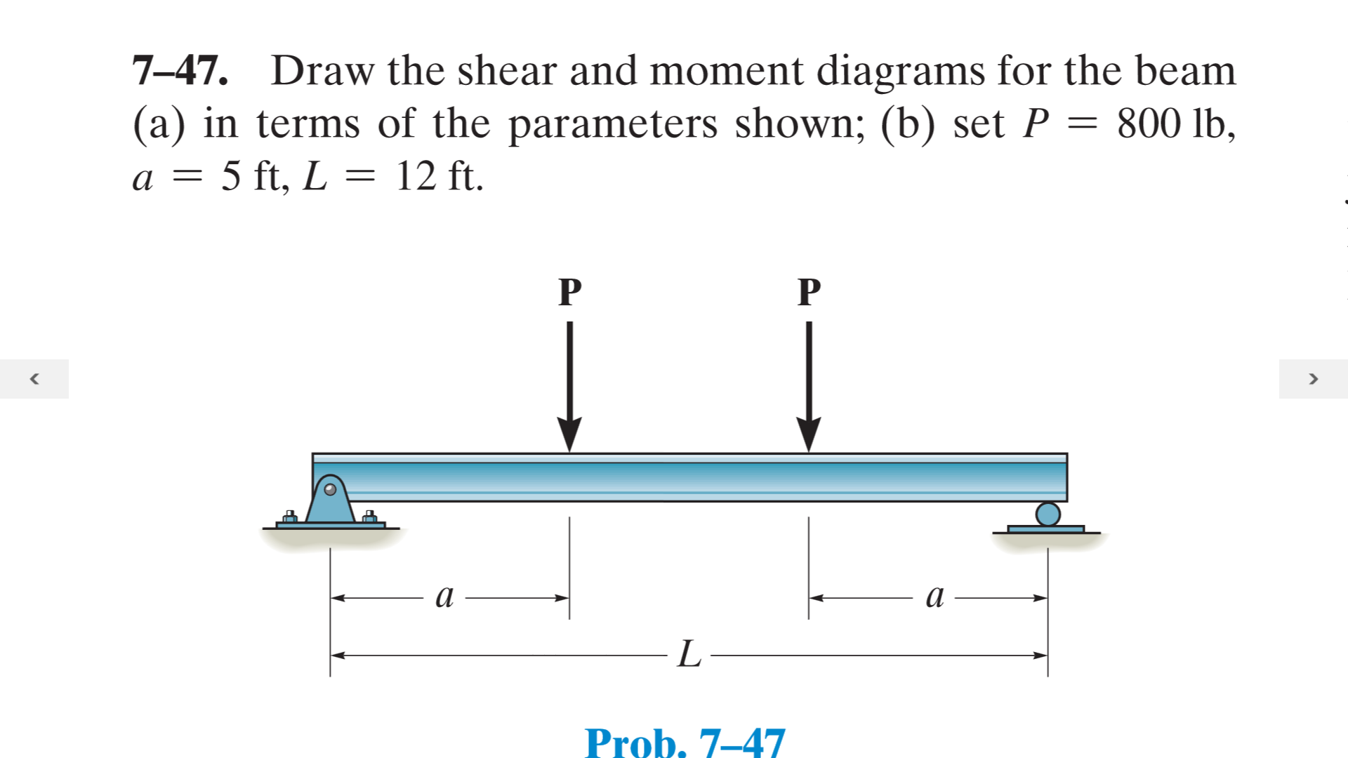
Solved Draw the shear and moment diagrams for the beam (a)
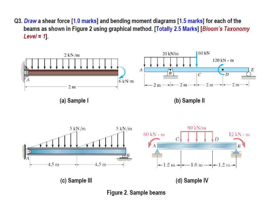
Shear and moment diagrams geekloki

Solved Draw the shear and moment diagrams for the beam.
Web The First Step In Calculating These Quantities And Their Spatial Variation Consists Of Constructing Shear And Bending Moment Diagrams, \(V(X)\) And \(M(X)\), Which Are The Internal Shearing Forces And Bending Moments Induced In.
Bending Moment Diagram (Bmd) Shear Force Diagram (Sfd) Axial Force Diagram (Afd) Frame Calculator.
Web Shear Force And Bending Moment Diagrams Are Powerful Graphical Methods That Are Used To Analyze A Beam Under Loading.
Skyciv Beam Tool Guides Users Along A Professional Beam Calculation Workflow, Culminating In The Ability To View And Determine If They Comply With Your Region's Design Codes.
Related Post: