Dimension Drawing, Choose your dimension type in the taskbar.
Dimension Drawing - Box, cone, cylinder, torus, sphere, and plane objects. It indicates direction and extent of a dimension. Dimensioning is vital in the engineering industry as it ensures that the final product meets the required standards and specifications. Web take a look at this drawing below: Web you may be required to sketch or read drawings constructed with either metric (si) or imperial dimensions. Such a dimensioning is represented mostly by. Web the process of adding size information to a drawing is known as dimensioning the drawing. In machine sketches and drawings, in which fractions and decimals are used for dimensions, the dimension line is usually broken near the middle to provide open space for the dimension numerals. Dimensioning should follow these guidelines. Our comprehensive guide covers techniques, standards, and best practices for accuracy and clarity. Web a comprehensive reference database of dimensioned drawings documenting the standard measurements and sizes of the everyday objects and spaces that make up our world. Such a dimensioning is represented mostly by. Web a comprehensive reference database of dimensioned drawings documenting the standard measurements and sizes of the everyday objects and spaces that make up our world. Web the process. This shows the length, breadth, and height. Web the general guideline is that each dimension should be placed on the view which shows the dimensioned feature most clearly, and which gives the clearest and least cluttered drawing. In this type of dimension, the external size of an object is represented. Web dimensioning a technical drawing refers to the process of. These measurements provide important information for understanding the object's size, proportions, and how its components relate to each other. This shows the length, breadth, and height. Choose your dimension type in the taskbar. Web a comprehensive reference database of dimensioned drawings documenting the standard measurements and sizes of the everyday objects and spaces that make up our world. Web dimension. Web there are two types of writing dimensions on a drawing. When you click on the dimension tool, it opens the. Scaled 2d drawings and 3d models available for download. Web geometric dimensioning and tolerancing (gd&t) is a system of symbols and standards used in engineering drawings and models to specify the required form, size, orientation, and location of parts. Our comprehensive guide covers techniques, standards, and best practices for accuracy and clarity. Web dimension and extension lines (figure 6) are thin, solid lines that show the direction, length, and limits of the dimensions of a part. This shows the length, breadth, and height. Dimensioning should follow these guidelines. Dimension lines are drawn with an arrowhead at both ends. In this article, we are going to talk about dimensions. Web just adding dimensions in a drawing is not always sufficient and if you want the machinist, architect or stakeholders to read your drawing exactly the same way every time then you should follow the dimensioning best practices as outlined in. Web the best way to get exact dimensions from. Any measurements that you need should be somewhere on the drawings. Web take a look at this drawing below: It indicates direction and extent of a dimension. Web the process of adding size information to a drawing is known as dimensioning the drawing. Geometrics is the science of specifying and tolerancing the shapes and locations of features on objects. Web essentially, dimensioning refers to the process of specifying the exact size, shape, and location of different parts and features on an engineering drawing. These are indicated on the engineering drawing to define the size characteristics such as length, height, breadth, diameter, radius, angle, etc. Web take a look at this drawing below: Web you may be required to sketch. Basic shapes are the building blocks for many staging background components and dimension lets you create several customizable shape objects: Web learn everything you need to know about dimensioning engineering drawings. Dimensioning should follow these guidelines. All of these building blocks are equally important for defining the drawing clearly and unambiguously. In order that size information is communicated as clearly. In machine sketches and drawings, in which fractions and decimals are used for dimensions, the dimension line is usually broken near the middle to provide open space for the dimension numerals. Our comprehensive guide covers techniques, standards, and best practices for accuracy and clarity. Web dimensions in engineering drawings are numerical values indicated graphically in a proper unit of measurement. In this article, we are going to talk about dimensions. Dimensioning is vital in the engineering industry as it ensures that the final product meets the required standards and specifications. Such a dimensioning is represented mostly by. Web open a project in the latest version of illustrator, then click on the dimension tool in the toolbar. Once the shape of a part is defined with an orthographic drawings, the size information is added also in the form of dimensions. Web a dimension is a numerical value expressed in appropriate units of measurement and used to define the size, location, orientation, form or other geometric characteristics of a part. Web a comprehensive reference database of dimensioned drawings documenting the standard measurements and sizes of the everyday objects and spaces that make up our world. Web you may be required to sketch or read drawings constructed with either metric (si) or imperial dimensions. Dimension lines are drawn with an arrowhead at both ends. All of these building blocks are equally important for defining the drawing clearly and unambiguously. Use the shape tools on the toolbar to draw a shape. Web the best way to get exact dimensions from drawings is to use the explicit dimensions (in millimeters or in feet and inches) written between the dimension lines. Web dimension and extension lines (figure 6) are thin, solid lines that show the direction, length, and limits of the dimensions of a part. Dimensioning should follow these guidelines. Web a convenient guide for geometric dimensioning and tolerancing (gd&t) symbols at your fingertips. Web the dimension line is a fine, dark, solid line with arrowheads on each end.
1.4aPlacing of Dimension Systems in Engineering Drawing Aligned and
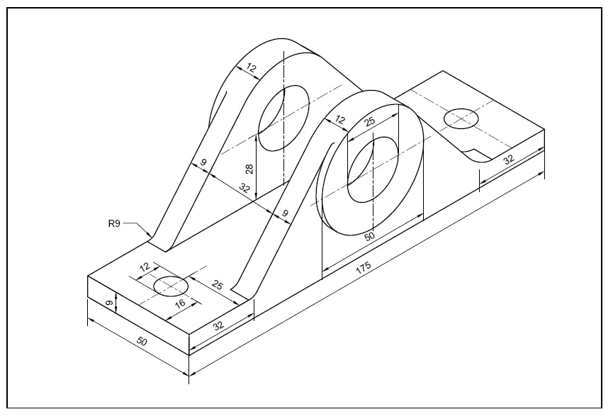
AutoCAD 3D Drawings with Dimensions for Practice 【Free CAD Download
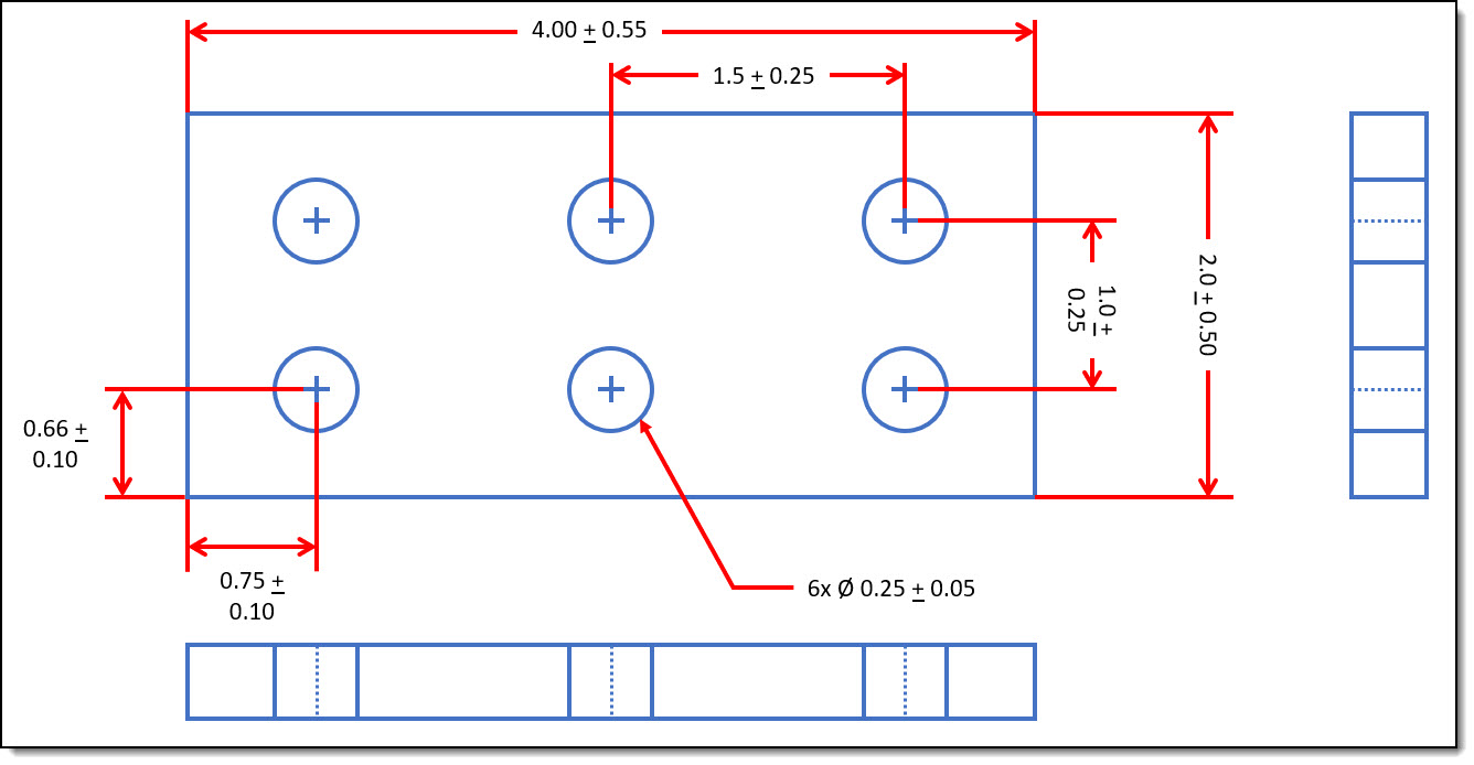
Engineering Drawings & GD&T For the Quality Engineer

Detailed Dimension Drawing 5 YouTube
Orthographic Projections With Dimensions OER
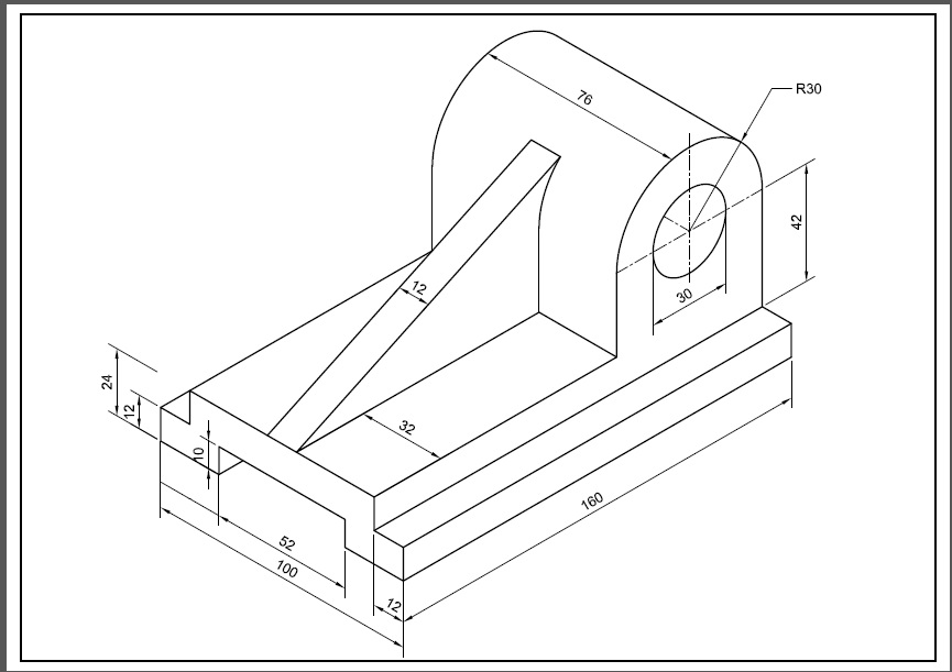
AutoCAD 3D Drawings with Dimensions for Practice
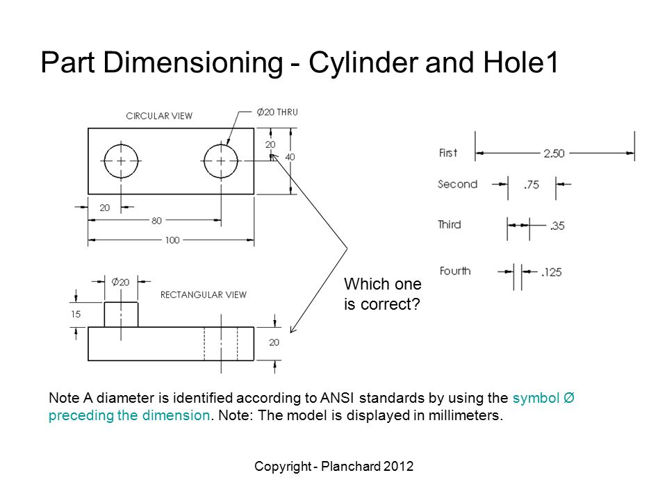
Drawing Dimension Symbols at Explore collection of

DRAWING BASICS

Detailed Dimension Drawing Using SolidWorks 2018 YouTube
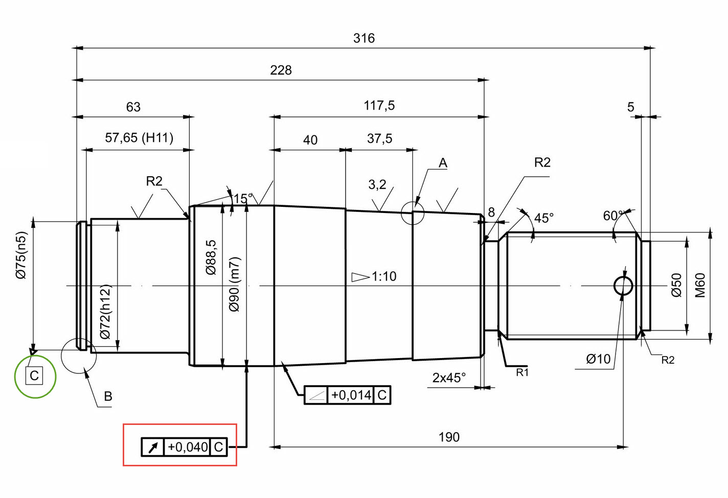
Drawing Dimension Symbols at Explore collection of
Web Learn Everything You Need To Know About Dimensioning Engineering Drawings.
Web Dimensioning A Technical Drawing Refers To The Process Of Adding Measurements And Numerical Values To Indicate The Size, Location, And Specifications Of Various Elements In The Drawing.
Web The Process Of Adding Size Information To A Drawing Is Known As Dimensioning The Drawing.
Click On The Links Below To Learn More About Each Gd&T Symbol Or Concept, And Be Sure To Download The Free Wall Chart For A Quick Reference When At.
Related Post: